


Installation, cont’d
MVX 44 / 48 / 84 / 88 VGA Matrix Switchers • Installation2-4
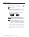
Video and audio output connections
2
RGB video output connectors — Connect RGBHV video
displays to these 15-pin HD female connectors for each output.
The MVX switchers can also switch RGBS, RGsB, RsGsBs, or
component/HDTV video.
The MVX switchers do not alter the video signal in any way. The signal
output by the switcher is in the same format as the input.
3
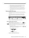
Balanced or unbalanced audio output connectors — These 3.5 mm, 5-pole
captive screw connectors output the selected unamplified, line level audio.
Connect audio devices, such as an audio amplifier or powered speakers, to
these connectors.
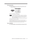
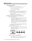
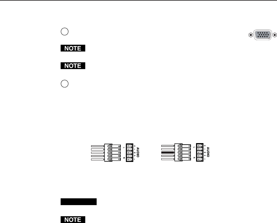
Figure 2-4 shows how to wire the captive screw audio connector. The
connector is included with the interface, but you must obtain the cable.
Insert the wires into the appropriate openings in the captive screw connector.
Tighten the screws on top to fasten the wires.
Unbalanced Output
Tip
See caution
Sleeve
Tip
See caution
Balanced Output
Tip
Ring
Sleeve (s)
Tip
Ring
Figure 2-4 — Captive screw connector wiring for audio output
CAUTION
Connect the sleeve to ground (Gnd). Connecting the sleeve to a negative
(–) terminal will damage the audio output circuits.
Figure 2-4 shows two methods of wiring the connectors for output. A mono
audio connector consists of the tip and sleeve. A stereo audio connector
consists of the tip, ring, and sleeve. If you are wiring a captive screw
connector from an existing unbalanced audio cable, the white insulated wire is
typically the left channel (tip) and the red insulated wire is typically the right
channel (sleeve). There is no reliable standard for existing balanced audio
cables.
The audio level for each input can be individually set, via the front panel or
RS-232, to ensure that the level on the output does not vary from input to
input. See chapter 3, Operation, and chapter 4, Remote Operation, for details.
By default, the audio follows the video switch. Audio breakaway, which is
commanded via the front panel, via RS-232 control using SIS commands or
the Windows-based control program, or via optional IR 501 control, allows
you to select from any one of the audio input sources. For details, see
chapter 3, Operation, and chapter 4, Remote Operation, and refer to the IR 501
User’s Guide.