


PRELIMINARY
PCM 340 Installation Note, cont'd
2
PCM 340 Installation Notes
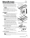
b. Measure the distances X and Y (see figure 2) from the inner
vertical section of the front and left T-frame runners to the
center of the Pipe Adapter Plate.
c. Using these dimensions, mark and cut a hole (using a 2 inch
hole saw) for the projector pipe in the ceiling tile (see figure 4).
d. If required, to prepare the ceiling tile for a power outlet, use
the PCM plate and trace and cut out the 2-gang hole in the
ceiling tile for a UL approved Raco junction box.
If this is not required, proceed to step 5.
T Install any optional power outlets in the 2-gang opening on
the mounting plate, towards the outside edge of the mount,
so they do not interfere with the PMK 550 when installed.
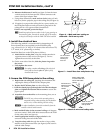
4. Install the electrical box.
The following method is recommended for integrating a 4S
Raco electrical box (not supplied) on the PCM base plate
(e.g., a Raco 231, 2 1/8" deep, 4"x4" electrical box and a Raco 778,
1/2" raised, 4"x4" plaster ring or similar).
Install the Raco box on the PCM plate as follows:
a. Attach the box to the plate, using the smallest notches in
opposite corners of the cut-out (see figure 5). Do not
tighten the screws fully at this time.
b. On the room side of the tile, slide the plaster ring under
the screws.
c. Fully tighten the screws
W For safety, complete all wiring of the electrical
boxes and accessories after the plate is fully
installed and secure.
5. Secure the PCM base plate to the ceiling.
a. Replace the cut ceiling tile, checking the orientation and
aligning the hole(s) with the PCM's adapter plate.
b. Replace the PCM base plate over the ceiling tile
c. Push the slotted pipe up through the hole into the adapter
plate and tighten the location and set screws to secure the
pipe in place.
d. Attach the four turnbuckles to the mounting plate, one at
each corner.
C DO NOT rest or lean on the mounting plate or
suspended ceiling when attaching the turnbuckles
and tie wire, or when drilling into the ceiling.
N For safest installation, insert the turnbuckle from the
outside so that it hooks inwards.
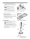
e. Mark and drill holes in the structural ceiling at 10 degrees
out from vertical. Drill a fifth hole centered above the PCM
for the safety cable (see figure 6).
f. Install appropriate anchors or lag eye bolts for the
structural ceiling into each drilled hole.
g. Loop the safety cable through the anchor or lag eye bolt,
attach it to the plate center holes (see figure 6) and secure it
with the cable clamps.
Use the smallest
notches when
attaching the
Raco box.
Raco 231
Raco 778
Figure 5 — Install Raco box and plaster ring
Attach safety cable
to center holes and
secure with cable
clamps.
Attach tie wire
to the turnbuckles
and eye bolts.
10
o
Drill holes and
attach tie wires
10° out from
vertical.
Figure 4 — Mark and start cutting on
underside. Finish on top side.
Figure 6 — Attach tie wire and safety cable
Underside
Top Side