


IMPORTANT:
Go to www.extron.com for the
complete system installation guide,
instructions, and specifications.
PMK 560 • Installation Guide
The Extron PMK 560 Pole Mount Kit, designed for use with the Extron PoleVault
™
System, allows
for easy mounting of PoleVault products to a projector pole. It is used to mount the PoleVault system switcher the associated
power supply and an accessory device within an enclosure and below a suspended ceiling.
CAUTION: Maximum load for the PMK 560 is 15 lbs (6.8 kg).
Items included in the kit are:
Covers (2), Base plate (1), Mounting plate (1),
Tie wraps and pads (to secure power supply)
4-40 Screws (to mount devices) (3),Cover Screws (4)
NOTE: For full device installation, configuration,
menus, connector wiring, and operation details of
the PoleVault switcher, see the PoleVault System
Installation Guide, available at www.extron.com.
Installation
To install the PMK 560 in a PoleVault system:
1. Remove the four cover screws from the center of the PMK 560
(see gure 1). Slide the two halves apart and remove them from
the base plate.
NOTE: If the PoleVault switcher and its power supply
are already installed, go directly to step 4.
2. To mount the PoleVault switcher, place the mounting plate, with
the raised tabs upwards, on the top surface of the switcher and
pass the two supplied 4-40 x 3/16 inch screws into the top of the
switcher (see gure 2, b). Secure the mounting plate but do not
overtighten.
3. Attach the associated power supply to the base plate with the
supplied tie wraps and pads, by passing them through the
appropriate slots and around the power supply (see gure 2 c).
Tighten until snug.
4. Loosen the four pipe collar set screws (see gure 2 d), and slide
the base plate up the pipe until it is touching the suspended ceiling.
5. Level the base plate and secure it by fully tightening the set screws.
NOTE: At least three set screws must come in contact
with the pipe.
6. Hook the combined plate and switcher into the PMK 560 base plate
(see gure 2, e). Secure it to the base plate with two screws.
ATTENTION: Use only supplied screws to avoid
damaging the switcher.
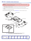
Figure 1. PMK 560
L R
DO NOT
GROUND
OR SHORT
SPEAKER
OUTPUTS
4/8
Ω
3A MAX
POWER
12V
HDMI
1/2
SIG
LINKSIG LINK
3/4
INPUTS
OUTPUT
AUDIO OUT
PVS 405SA IP
AMPLIFIED AUDIO OUT
PAGING
SENSOR
PVT IN
PVT IN
L
R
AUX
OVER PVT
REMOTE
VOICELIFT
LAN 1
LAN 2 LAN 3
INPUT 5
+V
L
R
RS-232
Tx
Rx
IR
SG G
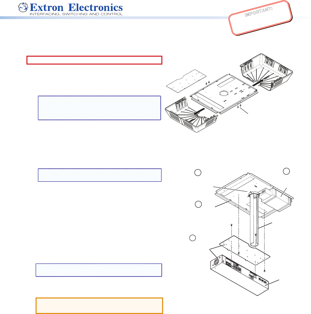
Attach Mounting plate
to the top of the
PoleVault switcher.
2
Hook the combined mounting
plate and switcher into the
base plate and secure with
screws.
3
Projector
Pole
Attach
Power
Supply
Attach PMK to the projector
pole pipe collar with the four
10-32 set screws.
PVS 405D
Switcher
4
5
PMK Covers (2)
Base Plate
To open, remove 4 cover scr
ews
and slide the covers away.
Mounting Plate
Figure 2. Attach the mounting plate to the switcher
and secure both to the base plate.