


68-2385-01 Rev. A
08 13
Extron Headquarters
+800.633.9876 (Inside USA/Canada Only)
Extron USA - West Extron USA - East
+1.714.491.1500 +1.919.850.1000
+1.714.491.1517 FAX +1.919.850.1001 FAX
Extron Europe
+800.3987.6673
(Inside Europe Only)
+31.33.453.4040
+31.33.453.4050 FAX
Extron Asia
+65.6383.4400
+65.6383.4664 FAX
Extron Japan
+81.3.3511.7655
+81.3.3511.7656 FAX
Extron China
+86.21.3760.1568
+86.21.3760.1566 FAX
Extron Middle East
+971.4.299.1800
+971.4.299.1880 FAX
Extron Korea
+82.2.3444.1571
+82.2.3444.1575 FAX
Extron India
1800.3070.3777
(Inside India Only)
+91.80.3055.3777
+91.80.3055.3737 FAX
© 2013 Extron Electronics All rights reserved. All trademarks mentioned are the property of their respective owners. www.extron.com
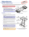
PMK 560 • Installation Guide (Continued)
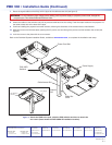
7. Route the signal cables so that they exit the pipe via the cable access slot (see gure 3).
WARNING: Do not thread any high voltage power cabling, such as power supply or projector power cords, through the
projector pipe. This violates National Electrical Code.
8. Attach the cables to the switcher and pull any excess cable back into the ceiling. Feed the output cables to the projector via
the cable access slot to the base of the pipe.
9. Continue installing the projector and other devices, following the directions of the relevant device manufacturer.
10. Slide the covers onto the base plate, passing the AC power cord out through the power cord slot between the covers (see
gure 3).
11. Lock the covers to the plate with the cover screws.
Refer to the PoleVault System Installation Guide, available at www.extron.com, to complete the installation and setup.
L R
DO NOT
GROUND
OR SHORT
SPEAKER
OUTPUTS
4/8
Ω
3A MAX
POWER
12V
HDMI
1/2
SIG LINK SIG
LINK
3/4
INPUTS
OUTPUT
AUDIO OUT
PVS 405SA IP
AMPLIFIED AUDIO OUT
PAGING
SENSOR
PVT IN
PVT IN
L
R
AUX
OVER PVT
REMOTE
VOICELIFT
LAN 1 LAN 2 LAN 3
INPUT 5
+V
L
R
RS-232
Tx
Rx
IR
S
G G
PVS 405D
Switcher
Projector
Pole
Cable Access Slot
Cable Slot
Cover
Power Supply
Power Cord Slot
PVS 305SA IP
Switcher
Power Supply
Figure 3. Attach the PMK to the pole, cable the PVS switcher and then re-attach the
two covers (inset shows the PVS 305SA IP installation location).