


Extron • MBC EVC Buffer • User’s Guide
Page 1
Operation and Installation Operation and Installation
Extron • MBC EVC Buffer • User’s Guide Page 2
MBC EVC Buffer
The MBC EVC Buffer adheres to the Multimedia configuration, per VESA
specifications. It provides a way to buffer the output of any computer that uses
the Enhanced Video Connector (EVC) to the input of an interface and the local
monitor.
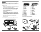
Installation Instructions
1. Power OFF the computer and Interface. Use the drawing below along with
the following steps to connect the MBC EVC Buffer.
2. Connect the Local Monitor (SUN, SILICON GRAPHICS, MAC, PC, NeXT
COLOR, or any other monitor that uses the EVC connector) to the Local
Monitor female output (A) on the MBC EVC Buffer.
3. Connect one end of the EVC cable (C) to the MBC EVC Buffer CPU
connector (B). Use cable connector C1 or C2.
4. Connect the other end of the EVC cable (C) to the monitor output of the
computer/Workstation.
5. Connect the Extron MBC EVC Buffer to the Extron analog interface using
the 9 pin D sub connector (D) and plug the 9 volt DC power plug (D1) into
the power jack. Set the Extron interface termination switch (if available) to
HIGH Z (unterminated).
6. Be sure that all cable connector screws are secure.
7. Plug the Interface power connector into an AC power receptacle.
8. Power ON the computer.
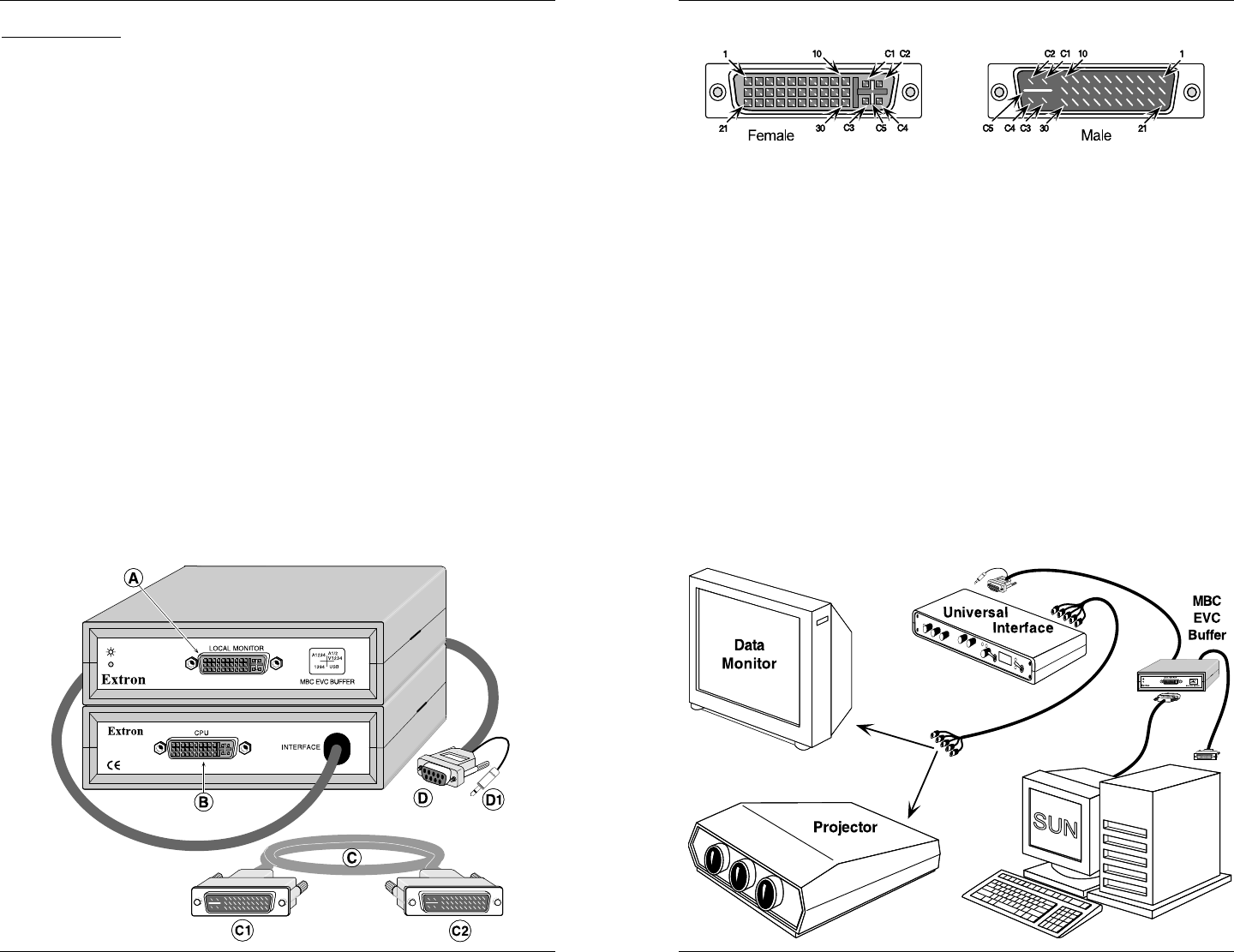
EVC connector pin assignments and a connection diagram are shown on the
facing page.
Connector (EVC) Pin Assignments
1 .. Audio Output, Right 16 .. USB data +
2 .. Audio Output, Left 17 .. USB data
−−
−−
−
3 .. Audio Output, Return *18 .. USB/1394 shield/chg rtn
4 .. Sync return 19 .. 1394 Vg
5 .. Horizontal Sync 20 .. 1394 Vp
6 .. Vertical Sync 21 .. Audio Input Left
7 .. Unused 22 .. Audio Input Right
*8 .. Charging pwr + 23 .. Audio Input Return
9 .. 1394 pair A,
−−
−−
− 24 .. Stereo Sync
10 .. 1394 pair A, + 25.. DDC Return
11 .. Reserved 1 26 .. DDC data (SDA)
12 .. Reserved 2 27 .. DDC clock (SCL)
13 .. Video input Y *28 .. +5 VDC
14 .. Video input return 29 .. 1394 pair B, +
15 .. Video input, C 30 .. 1394 pair B,
−−
−−
−
C1 .. Red video out C4 .. Blue video out
C2 .. Green video out C5 .. Video/pixel clock return
C3 .. Pixel clock out
*Pins 8, 18 and 28 are recessed in the cable end connector (plug)
to provide for proper power/ground sequencing.