


Extron • System 4
xixi
xixi
xi
Switcher Series • User’s Manual • P/N 68-424-02 Rev. D
Configuration and Connections
Epson Installation
Page 3
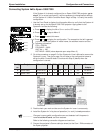
6. Connect the Epson Comm Adapter’s 9-pin female connector to the 9-pin male
connector of the projector cable. Connect the other end of the Comm Adapter to
the Communications Extension cable (CC-50’ or CC-100’).
7. Plug the 15-pin HD connector of the Communications Extension cable into the
PJ Comm port on the System 4xi.
______ Secure all of the connector screws.
8. Plug the (4 or 5) BNC connectors from one end of the (user-supplied) RGBS/HV
cable onto the System 4xi output and those on the other end onto the matching
BNCs on the Epson 5300/7300 connector panel.
9. Power on the System 4xi and the projector.
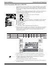
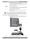
10. Press the projector’s Menu button. From the projector display, select Options
and enter this selection.
11. Select Mouse/Com 1, then select BNC Format RGB and enter this selection.
_ When the projector and switcher are communicating with each other, there will be a delay of
30 to 60 seconds when powering the projector on/off using the System 4
xi
. While waiting for
the projector to power on, the message
“ Pls Wait PRJ Dwn”
will display on the System 4
xi
’s
LCD
System 4
xixi
xixi
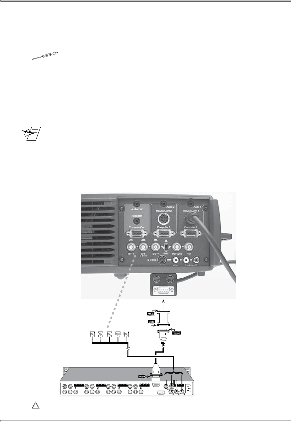
xi Series – Epson 5300/7300 Projector Connections
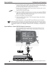
Use the illustration below as a guide when connecting the System 4xi to an
Epson 5300/7300 projector. Refer to Epson documentation to continue the
installation.
____________ In a rack mount, do NOT allow the weight of the cables to be supported by the
System 4
xi
. See page 2-5 for cabling guidelines.
9-Pin
Comm Adapter
26-484-01
"I"
CC 50'
3, 4 or 5 BNC
15-Pin
9-Pin
"I"