


LM RGB 103/109/112
xixi
xixi
xi Controls and Installation
Controls and Installation, cont’d
A
RGB 103/109/112
xixi
xixi
xi
Appendix A
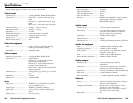
Specifications
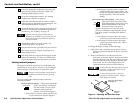
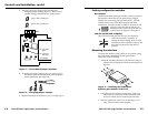
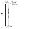
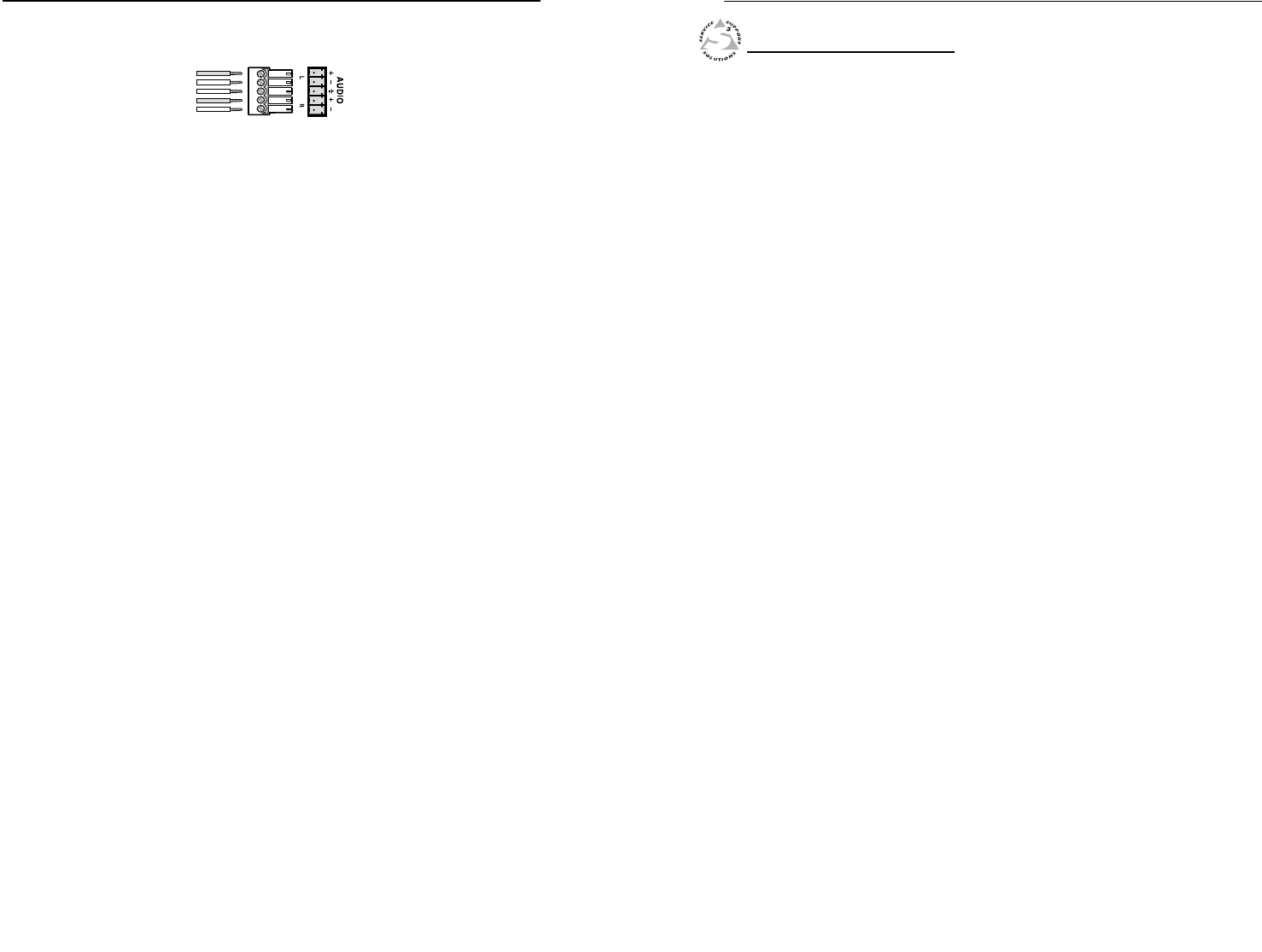
2. Attach the audio cable to the captive screw connector
(Extron part number
10-319-10). Fasten
the captive screws
inside the audio cable
connector as shown
in figure 16.
3. Slide the audio cable connector into the audio output
connector on the interface.
Balanced Output
Tip
Ring
Sleeve (s)
Tip
Ring
2-14