


RGB 160xi and RGB 164xi • Controls and Installation
Controls and Installation, cont’d
2-8
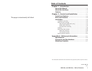
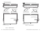
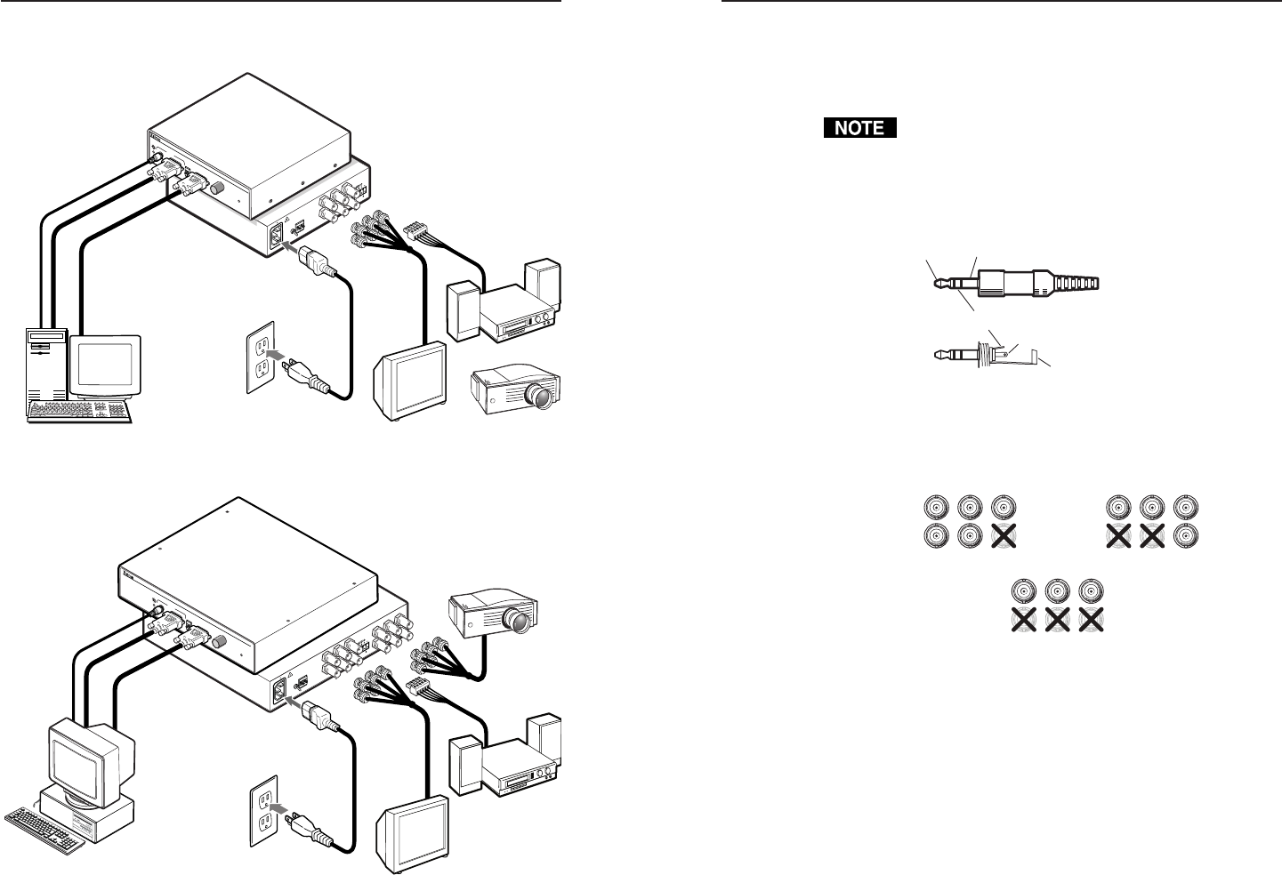
Cabling
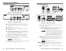
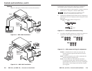
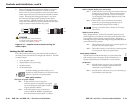
Figure 2-9 and figure 2-10 show how to connect the interfaces.
PC Computer
Monitor Projector
Audio
Power
or
O
U
T
P
U
T
SOG OUT
DDSP
SERR
SPARE
Rear
5
0
/
6
0
H
z
1
0
0
-
2
4
0
V
0
.
5
A
L
E
V
E
L
/
P
E
A
K
0
.
8
V
5
0
%
U
N
I
T
Y
0
.
9
V
1
0
0
%
IN
P
U
T
R
G
B
1
5
0
x
i
U
N
IV
E
R
S
A
L
IN
T
E
R
F
A
C
E
W
/A
D
S
P
Front
H
.
S
H
IF
T
M
IN
/M
A
X
I
D
P
I
N
4
I
D
P
I
N
1
1
A
U
D
IO
Extron
RGB 160xi
Interface
Figure 2-9 — RGB 160xi installation
Monitor
Projector
Output 2
Output 1
Audio
Power
or
Extron
RGB 164xi
Interface
OUTPUT
SOG OUT
DDSP
SERR
SPARE
Rear
5
0
/
6
0
H
z
1
0
0
-
2
4
0
V
0
.
5
A
L
E
V
E
L
/
P
E
A
K
0
.
8
V
5
0
%
U
N
I
T
Y
0
.
9
V
1
0
0
%
PC
INPU
T
RGB 164 xi
UNIVERSAL INTERF
A
CE
W /ADSP
Front
H.
SHIFT
ID
P
IN
4
ID
P
IN
11
A
U
D
I
O
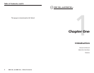
Figure 2-10 — RGB 164xi installation
RGB 160xi and 164xi • Controls and Installation
Each interface can connect to the computer or workstation’s
local monitor and to a projector or other display device.
1. Connect the computer to the interface’s "Analog" connector
(RGB 160xi) or "Computer" connector (RGB 164xi).
Extron does not guarantee the performance of the
interface if a low quality input cable is used.
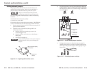
2. Connect the unbalanced stereo audio sources (computer or
other devices such as a CD player) to the front panel Audio
Input jack.
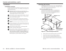
Wire the audio jack as shown in figure 2-11.
Figure 2-11 — Audio input connection wiring
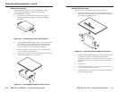
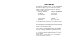
3. Use cables with BNC connectors to connect the interface to
a projector or other display device(s) (figure 2-12).
Figure 2-12 — Video output wiring pin assignments
RGBHV – If both the H & V cables are connected, the
interface outputs separate horizontal and vertical
sync signals.
RGBS – If the S (composite sync) cable is connected, the
interface outputs composite sync.
RGsB – If coax cables are connected and terminated
(75 ohms) to the red, green, and blue channels only,
and the SOG OUT switch is set to on (see "Setting the
DIP switches" in this chapter), the interface outputs
sync on green.
2-9
Tip (+) Sleeve
Tip (+)
Ring (-)
Sleeve
RGBS
Video
R
H
G
V
B
S
RGBHV
Video
R
H
G
V
B
S
RGsB
Video
R
H
G
V
B
S