


Setup Guide — RGB 160xi and RGB 164xi (cont’d)
Extron USA - West
Headquarters
+800.633.9876
Inside USA / Canada Only
+1.714.491.1500
+1.714.491.1517 FAX
Extron USA - East
+800.633.9876
Inside USA / Canada Only
+1.919.863.1794
+1.919.863.1797 FAX
Extron Europe
+800.3987.6673
Inside Europe Only
+31.33.453.4040
+31.33.453.4050 FAX
Extron Asia
+800.7339.8766
Inside Asia Only
+65.6383.4400
+65.6383.4664 FAX
Extron Japan
+81.3.3511.7655
+81.3.3511.7656 FAX
Extron China
+400.883.1568
Inside China Only
+86.21.3760.1568
+86.21.3760.1566 FAX
Extron Middle East
+971.4.2991800
+971.4.2991880 FAX
© 2010 Extron Electronics. All rights reserved.
68-549-50
Rev. A
02 10
100-240V 0.5 A MAX
50-60Hz
UNITY
50%
100%
GAIN/
PEAK
SOG
DDSP
SERR
SPARE
L R
AUDIO
R
G
B
H
V
S
OUTPUT 2OUTPUT 1
R
G
B
H
V
S
8 109 13
11 12
N
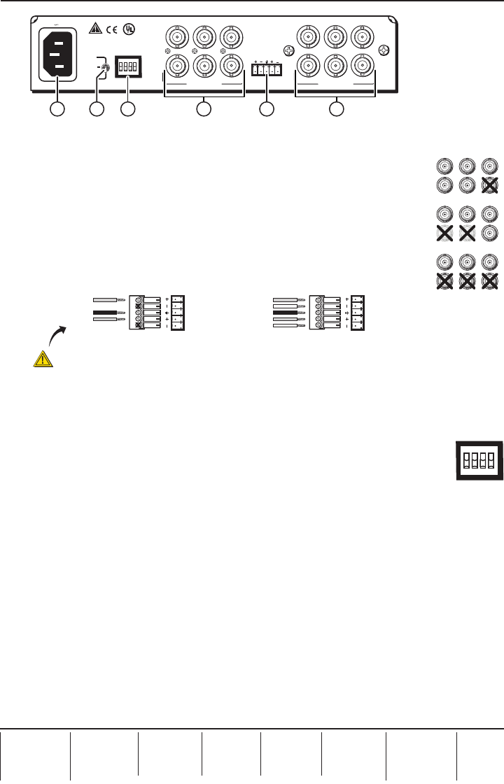
This figure shows the RGB 164xi rear panel. The features of the RGB 160xi rear panel are
similar except there is no Output 2 (
l
).
Step 7 — Connect video output(s)
Connect the RGBHV, RGBS, or RGsB video displays to Output 1 (
k
) and,
if required, Output 2 (
l
— RGB 164xi only), as shown in the figure at
right.
Step 8 — Connect audio output
Connect an audio device to the five-pole, 3.5 mm captive screw connector
(
m
). Follow the wiring diagram below for unbalanced or balanced stereo
output.
Unbalanced Stereo Output
Tip
NO GROUND HERE.
Sleeve(s)
Tip
NO GROUND HERE.
Balanced Stereo Output
Tip
Ring
Sleeve(s)
Tip
Ring
L R
L R
Left
Right
Left
Right
CAUTION
For unbalanced audio, connect the sleeve(s) to the center contact ground.
DO NOT connect the sleeve(s) to the negative (-) contacts.
Step 9 — Connect power
Connect a standard IEC AC power connector (100-240 VAC, 50-60 Hz) to this socket (
i
).
Power on input and output devices.
Step 10 — Set rear panel DIP switches
The first three rear panel DIP switches (
j
) control:
Sync on Green (SOG) — Set to on (up) for RGsB output; set to off for RGBHV or
RGBS output.
Digital Display Sync Processing (DDSP
™
) — Set to off (down) for sync processing; set to on
(up) for no sync processing (may be needed for some LCD and DLP plasma displays) .
Serration Pulses — Set to on (up) to keep serration pulses; set to off to remove them. If there is
flagging or bending at the top of the video image, set this switch to off.
N
Turning on the DDSP switch disables the horizontal shift.
Step 11 — Set rear panel Gain/Peak switch
This rear panel switch (
i
) can be set to Unity (no gain and no peaking), gain with 50%
peaking, gain with 100% peaking. For cable runs of 125 feet or less, use the Unity setting.
Step 12 — Set front panel DIP switches
These front panel ID bit termination DIP switches (
d
) must both be set to on (up) if using a
laptop and no local monitor. Both switches must be set to off if using a local monitor.
Step 13 — Adjust horizontal shift
This front panel knob (
f
) adjusts the horizontal shift of the remote output display device(s).
RGBS
Video
R
H
G
V
B
S
RGBHV
Video
R
H
G
V
B
S
RGsB
Video
R
H
G
V
B
S
SOG
DDSP
SERR
SPARE