


RGB 190F, RGB 192, and RGB 198 • Installation and Operation
RGB 190F, RGB 192, and RGB 198 • Installation and Operation
Installation and Operation, cont’d
2-6 2-7
LISTED
1T23
I.T.E
RGB
OUTPUT
HVS
100-240V 10.5-3.6A MAX
150/60Hz
ANAHEIM, CA
MADE IN USA
L/MONO R
AUDI O
H-SHIFT
SERR
DDSP
NO MON.
M. AUDIO
SOG
LEVEL
COMPUTER
INPUT
MONITOR
OUTPUT
AUDI O
1
ON
2
3
4
5
6
125V 50/60 Hz 5A 125V 50/60 Hz 5A
RGB 198
UNIVERSAL INTERFACE
2
1
6
5
4
3
9
8
10
11
12
13
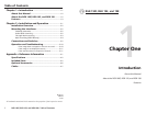
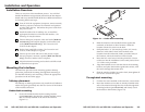
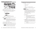
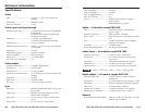
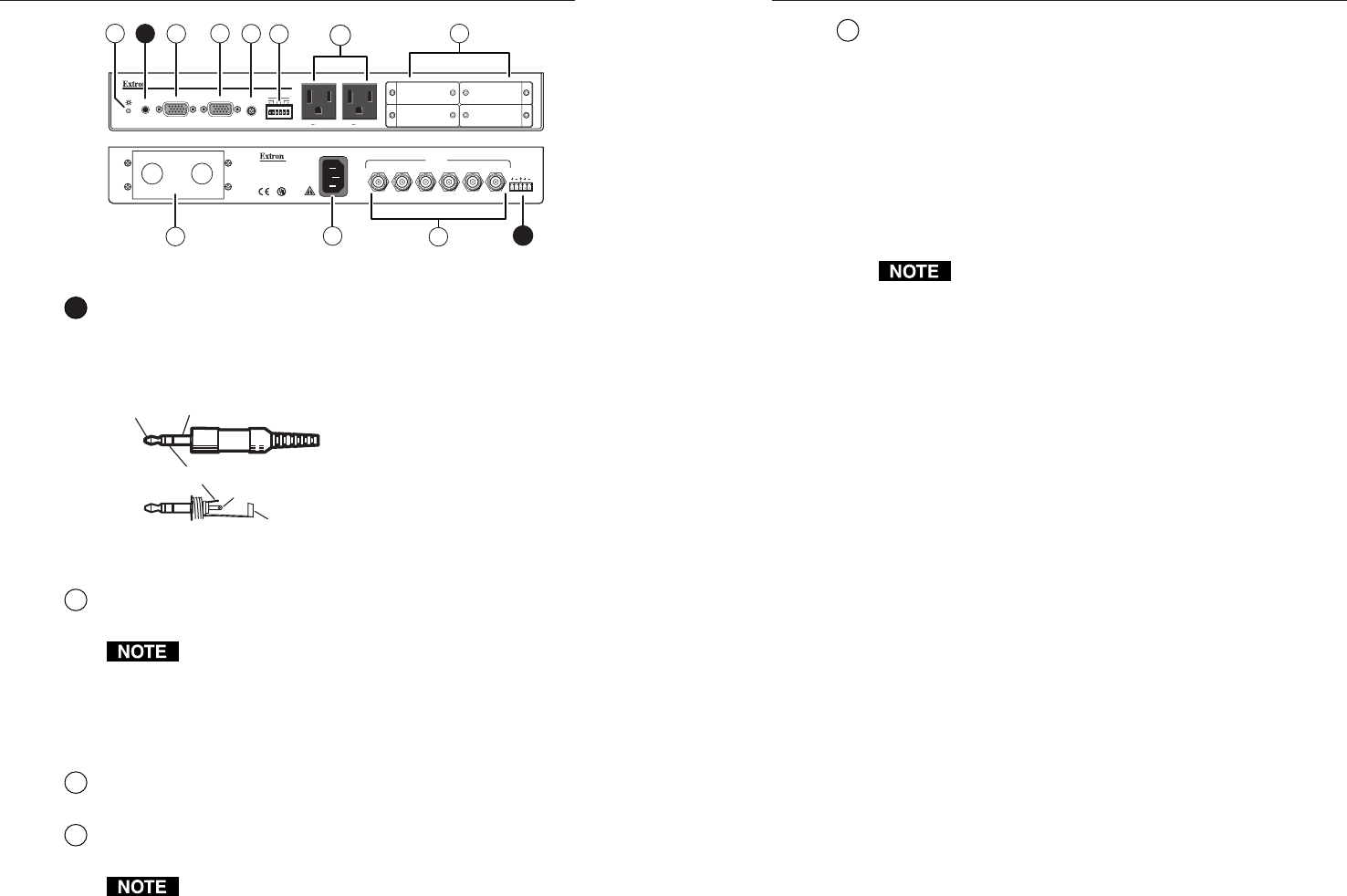
Figure 2-5 — RGB 198 front and rear panel features
2
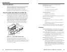
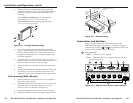
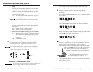
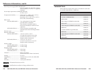
Audio input (RGB 192 and 198 only) — Connect the
unbalanced stereo audio source (such as a computer or a CD
player) to this 3.5 mm mini stereo jack for unbalanced audio
input. Figure 2-6 shows how to wire the audio jack.
Tip (Left
)
Sleeve (Gnd)
Tip (Left)
Ring (Right)
Sleeve (Gnd)
Figure 2-6 — Audio input connector wiring
3
Computer Input — Connect the analog computer-video source
to this 15-pin HD female connector.
Most laptop or notebook computers have an external
video port, but they require special commands to output
the video to that connector. Also, laptops’ screens shut
off once that port is activated. See the computer’s user’s
guide for details, or contact Extron for a list of laptop
keyboard commands.
4
Monitor Output — If desired, connect a local monitor or other
device to this 15-pin HD female connector.
5
H(orizontal) Shift — While viewing the displayed image, rotate
this control to move the image to the right or left on the screen.
DDSP disables the interface’s Horizontal Shift control.
To use the display’s centering controls instead of the
interface’s controls, set the DDSP DIP switch to On.
6
DIP switches — This bank of DIP switches is used to configure
the interface. The switches control:
• Level
• SOG (sync on green)
• Serration pulses
•DDSP
• Monitor or no monitor (ID bit termination)
•
Mono or stereo audio (
RGB 192 and 198 only
, spare on
RGB 190F)
The default for all DIP switches is Off (down).
1 — Level (and peaking)
The Level control alters the video output voltage to affect
the brightness of the displayed image. Turn the switch on
and off while viewing the displayed image to set the level
that provides the best picture quality. If the interface
receives a typical (0.7 volts p-p) analog computer video
input, the output is as follows:
On — 0.8 volts p-p with peaking
Off — 0.7 volts p-p
2 — Sync on green
On — The interface outputs a composite sync signal on
top of the green video signal (SOG) via the G
output connector (RGsB).
Off — The interface outputs separate horizontal and
vertical sync (on the H and V connectors) and
composite sync (on the S connector) for RGBHV or
RGBS.
3 — Serration pulses — Many LCD and DLP projectors and
plasma displays do not display properly if serration pulses
are present in the sync signal. Flagging or bending at the
top of the video image is a sign that the serration pulses
should be removed.
On — The interface outputs serration pulses in the vertical
sync interval.
Off — The interface does not output serration pulses.