


RGB 190F, RGB 192, and RGB 198 • Installation and Operation
RGB 190F, RGB 192, and RGB 198 • Installation and Operation
Installation and Operation, cont’d
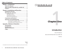
2-52-4
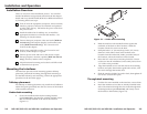
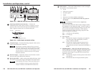
3. Hold the interface with attached brackets against the
underside of the desk/table. With a soft pencil mark the
location of holes for screws on the desk based on the
following:
For the RGB 190 and RGB 192, mark the opening
approximately 1.0" x 5.7" ( 2.5 cm x 14.5 cm).
For the RGB 198, mark the opening approximately
1.75" x 13.0" (4.5 cm x 33.0 cm).
M
O
N
IT
O
R
H
-
S
H
IF
T
S
E
R
R
D
D
S
P
N
O
M
O
N
.
M
.
A
U
D
IO
S
O
G
L
E
V
E
L
R
G
B
1
9
2
C
O
M
P
U
T
E
R
A
U
D
IO
1
O
N
2
3
4
5
6
Figure 2-2 — Through-desk mounting
4. Cut out the material from the installation area with a
jigsaw. Check the opening size by inserting the interface
part way through the hole. If needed, use a saw, file or
sandpaper to enlarge the hole. Smooth the edges of the
hole with sandpaper.
5. Drill pilot holes 1/4" (6.4 mm) deep, and 3/32" (2 mm)
diameter in the underside or inside (concealed side) of the
furniture where the interface will be located.
6. Secure the interface to the desk with the provided wood
screws.
7. To adjust the height of the interface within the desk, slide
the interface up or down to the desired position, then
tighten the screws that attach the brackets to the interface.
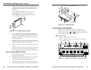
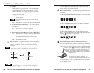
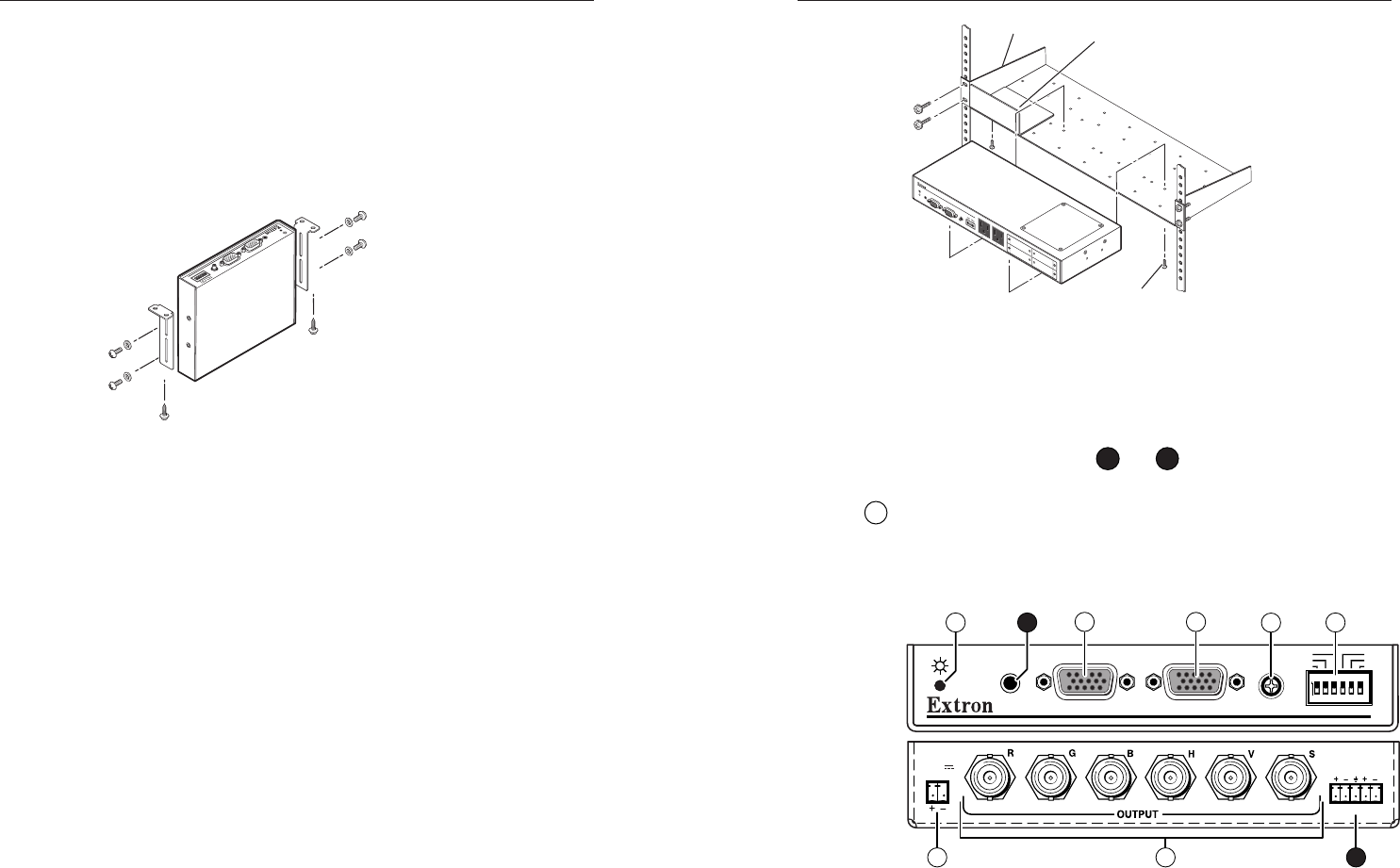
Rack mounting (RGB 198 only)
1. Remove rubber feet if they were previously installed on
the bottom of the interface.
2. Mount the interface on either side of an 19" 1U Universal
Rack Shelf (part # 60-190-01) using two 4-40 x 3/16"
screws to secure it to the shelf. See figure 2-3.
3. Install blank panel(s) or other unit(s) on the rack shelf.
4. Attach the rack shelf to the rack using the supplied bolts.
6" Deep Rack Shelf
Front false
faceplate
uses 2
screws.
1/4 Rack Width Front False
Faceplate
Use 2 mounting holes.
(2) 4-40 x 3/16"
Screws
H
-
S
H
I
F
T
S
E
R
R
D
D
S
P
N
O
M
O
N
.
M
.
A
U
D
IO
S
O
G
L
E
V
E
L
C
O
M
P
U
T
E
R
I
N
P
U
T
M
O
N
I
T
O
R
O
U
T
P
U
T
A
U
D
IO
1
O
N
2
3
4
5
6
1
2
5
V
50
/6
0
H
z
5
A
1
2
5
V
50
/6
0
H
z
5
A
R
G
B
1
9
8
U
N
I
V
E
R
S
A
L
I
N
T
E
R
F
A
C
E
Figure 2-3 — Rack mounting
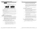
Connections and Switches
Figures 2-4 and 2-5 show the front and rear panel of the
RGB 192 and the RGB 198, respectively. With the exception of
audio features (numbers
2
and
9
), all numbers for figure 2-4
pertain to both the RGB 190 and 192 models.
1
Power indicator —
Amber — Indicates power is applied.
Green — Indicates that power is applied and a sync signal is
present on the input.
H-SHIFT
SERR
DDSP
NO MON.
M. AUDIO
SOG
LEVEL
RGB 192
COMPUTER
INPUT MONITOR
L/MONO
R
AUDIO
AUDIO
1
ON
2
3
4
5
6
POWER
12-15V
1A MAX.
7
21
3
6
9
4
5
8
Figure 2-4 — RGB 192 front and rear panel features