


RGB 400
xixi
xixi
xi Series Installation Guide
Installation, cont’d
10
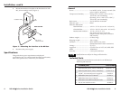
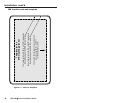
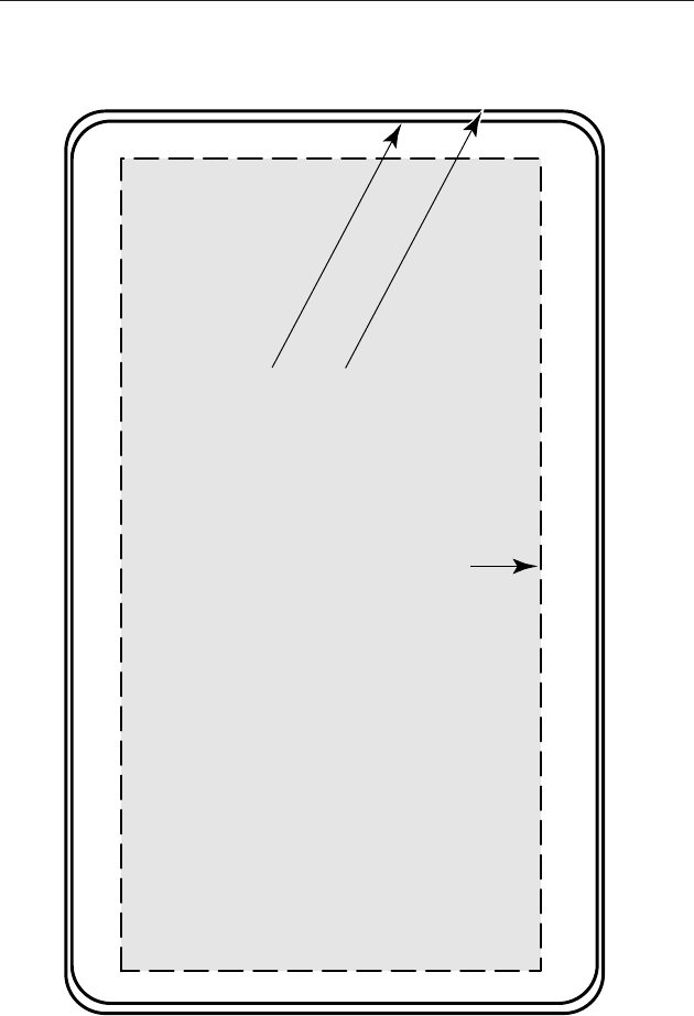
The dashed line indicates the recommended
cut-out area (2.68” H x 5.25” W)
for the installation surface.
The inside solid line (3.38” H x 5.70” W) represents
the outside edge of the RGB 460xi wall plate.
Template for the
MK mounting bracket
The outside solid line (3.5” H x 5.83” W) represents
the outside edge of the RGB 472xi wall plate.
MK Interface cut-out template
Figure 6 — Cut-out template