


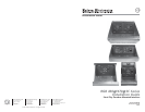

RGB 460
xixi
xixi
xi/470
xixi
xixi
xi SC Series • Installation GuideRGB 460
xixi
xixi
xi/470
xixi
xixi
xi SC Series • Installation Guide
Installation, cont’d
2
Installation Instructions
CAUTION
The interface must be installed into an
Underwriters Laboratories (UL) approved Steel
City electrical floor box. The floorbox is not
included with the interface; the installer is
responsible for obtaining and installing the box.
Preparing the site and cables
Choose a location that allows cable runs without interference.
Allow enough depth for both the floorbox and the cables. You
need to run the conduit (if required by local code) and cables
under the floor before installing the interface.
The installation must conform to national and local electrical
codes and to the interface’s size requirements. Dimensional
drawings and actual-size cut-out templates are provided at the
end of this guide.
1. Install the floorbox in accordance with the documentation
that accompanied the box.
2. Feed cables through the floorbox punch-out holes, and
secure them with cable clamps to provide strain relief.
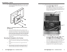
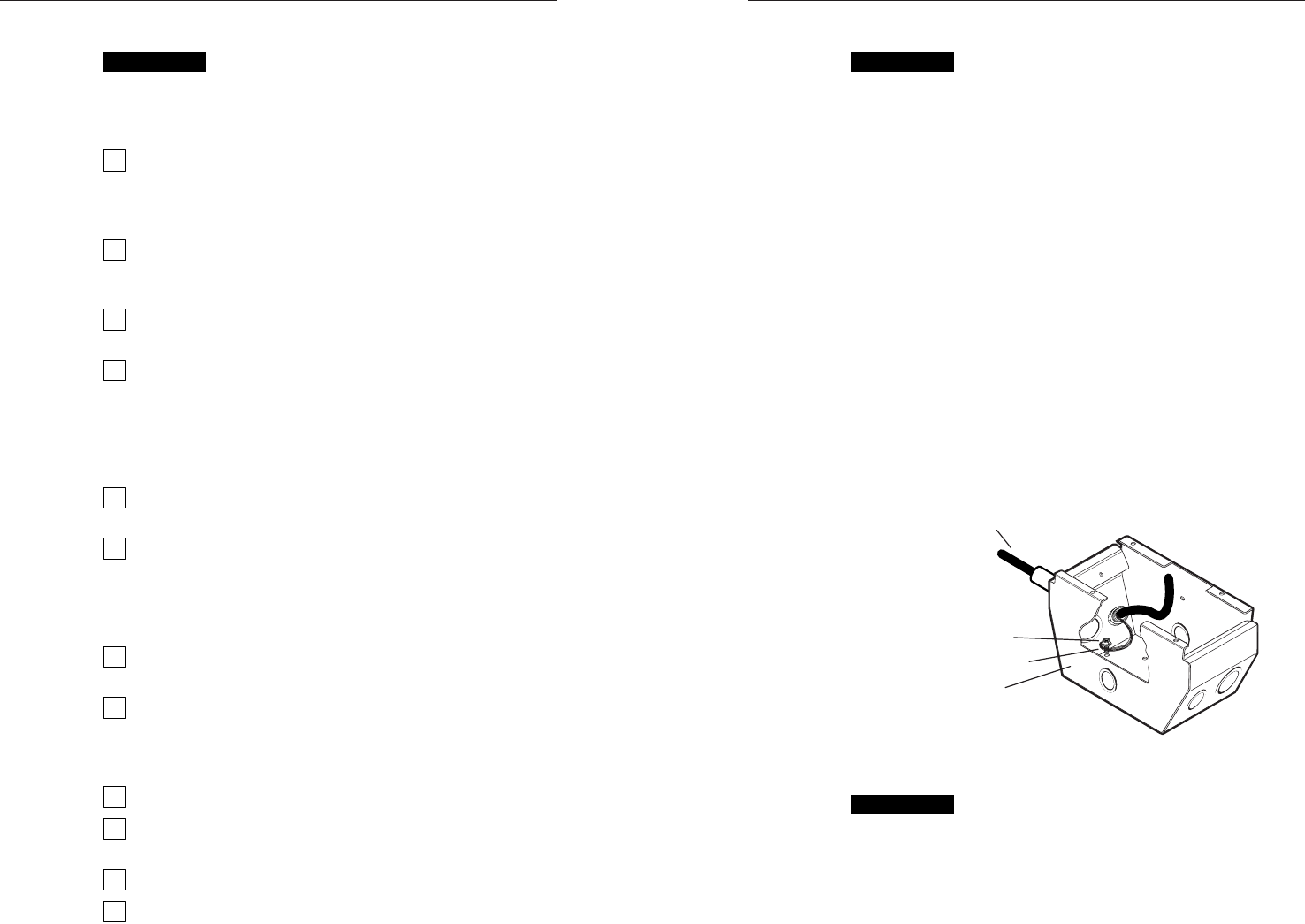
3. Exposed cable shields (braids or foil) are potential sources
of short circuits. Trim back and/or insulate shields with
heat shrink (figure 1).
Installation Cable
Steel City Box
Screw
Braided Shield
Figure 1 — Grounding outer braided and foil
shields, AFM 2 box
CAUTION
To prevent short circuits, the outer foil shield can be
cut back to the point where the cable exits the cable
clamp. Both braided and foil shields should be
connected to an equipment ground at the other end
of the cable.
3
Installation Overview
CAUTION
Installation and service must be performed by
authorized personnel only. These products must be
used with UL approved electrical boxes.
Install the interface as follows:
1
Turn all of the equipment off. Make sure that the
computer, the interface, and the output devices (projector/
monitor, speakers) are all turned off and disconnected
from the power source.
2
Select the installation location and install the electrical
floorbox. Refer to the documentation that was included
with the floorbox.
3
Route the cables that connect to the rear of the interface (or
the device(s) to be installed in the SC-AFM8 adapter plate).
4
Set the gain and DIP switches (or the switch(es) on the
rear of the device(s) to be installed in the SC-AFM8
adapter plate). Refer to the RGB 400xi Series User Manual,
Part #68-542-01, the RGB 470xi Series User Manual, Part
#68-661-01, (or the appropriate manual(s) for the device(s)
to be installed in the SC-AFM8 adapter plate).
5
For the SC-AFM8 adapter plate only, secure the device(s)
to be installed to the front of the faceplate.
6
Connect the video, audio, and power cables to the rear of
the device. Refer to the RGB 400xi Series User Manual,
Part #68-542-01, the RGB 470xi Series User Manual, Part
#68-661-01, (or the appropriate manual(s) for the device(s)
to be installed in the SC-AFM8 adapter plate).
7
Connect power cords and turn on the projector or monitor
and audio device, the interface, and the computer.
8
The picture should now appear, and sound should be
audible. If not, ensure that all devices are plugged in and
receiving power. Check the cabling and switch settings,
and make adjustments as needed.
9
Disconnect power from all the devices.
10
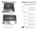
Mount the faceplate into the electrical box. See Mounting
the faceplate to the floorbox in this manual.
11
Restore power to the devices.
12
For the SC-AFM8 adapter plate only, as necessary, secure
blank 1-gang faceplate(s) to the front of the faceplate.