


RGB 580
xixi
xixi
xi AAP • Installation and Operation
Installation and Operation
RGB 580
xixi
xixi
xi AAP • Installation and Operation 54
RGB 580
xixi
xixi
xi AAP • Installation and Operation
Part Numbers
RGB 580
xixi
xixi
xi AAP • Installation and Operation
76
Part Numbers
Installation and Operation
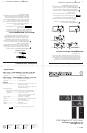
Example of mounting an AAP device to a wallplate
Cabling the AAP/Cable Cubby AAP Device
Rear Connectors
Extron’s various AAP/Cable Cubby AAP devices for the
RGB 580xi may come with several rear connectors that may
require cabling.
Although the control cable, LED, and audio assemblies
will come prewired (AAP only) to the captive screw
connectors, any subsequent cable assembly replacement
will require the following cabling instructions.
To cable the captive screw connectors, please refer to the
following diagrams and orient the wires according to the view
angle of the captive screws. When using Extron’s VGA and
control cable assembly (see the “Cables” section for part
numbers), refer to the color of each wire for signal identification.
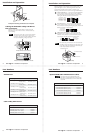
1
Control connector (J4) — Insert wires into and tighten the
screws on this 3.5 mm, 5-pole captive screw connector.
This connector is used for contact closure and horizontal
shift signals. Wire the connector as shown below.
2
LED connector (J2) — Insert wires into and tighten the
screws on this 3.5 mm, 3-pole captive screw connector.
This connector is used for powering the green/amber LED.
Wire the connector as shown below.
3
Audio output connector (J3) — Insert wires into and
tighten the screws on this 3.5 mm, 3-pole captive screw
connector. This connector is used for unbalanced stereo
audio output. Wire the connector as shown below.
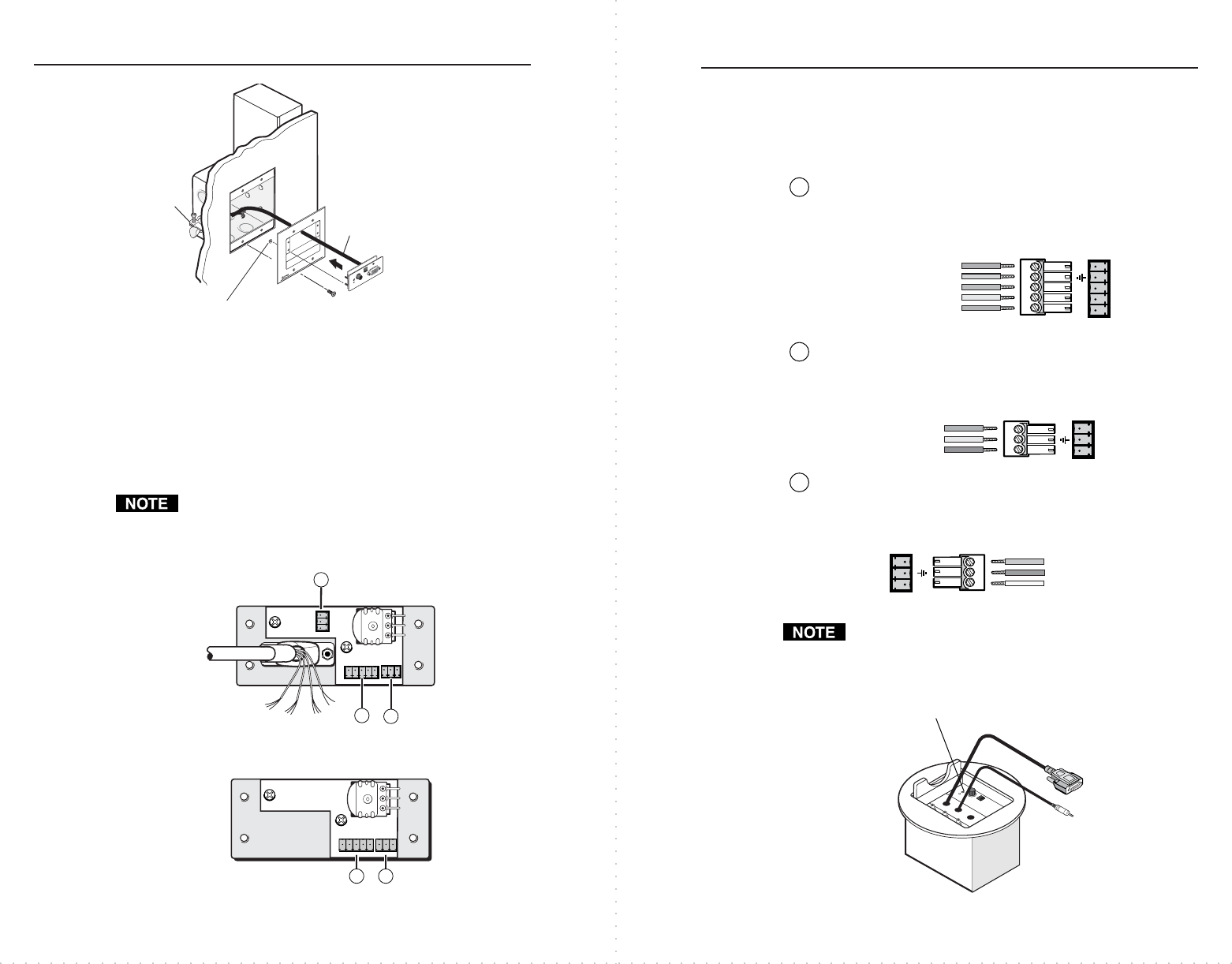
On Cable Cubby AAP models, the VGA and audio cable
assemblies will be routed through the Cable Cubby. Refer
to the Cable Cubby User’s Manual (part #68-701-01) for
Cable Cubby installation instructions.
RGB 580
xi
CCSI AAP
Cable Cubby
CC AAP VGA connector
CC AAP Audio connector
IN
PU
T
S
E
LE
C
T
H
. S
HIFT
1
3
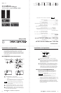
Example of AAP device rear connectors
2
J4 J2
J3
Red
Black
White
Yellow
Pink
Orange
Green
Gray
Brown
Lt. Blue
Purple
Green LED (pink)
LED ground (yellow)
Amber LED (orange)
LED
1 2 3
Audio right (red)
Audio ground (black)
Audio left (white)
R+
L+
Audio
1 2 3
Horizontal shift
+
(green)
Horizontal shift ground (gray)
Horizontal shift
–
(brown)
Contact closure
+
(light blue)
Contact closure
–
(purple)
Control
1 2 3 4 5
Cable
Cable
Clamp
RGB 580xi SI AAP
AAP 102
A
A
P
1
0
2
#4-40 Nut w/ Captive
Washer
R
G
B
5
8
0
x
i
S
I
A
A
P
CO
M
PU
TE
R
A
U
D
IO
H
S
H
IF
T
I
N
P
U
T
S
E
L
E
C
T
J4 J2
Example of Cable Cubby AAP device rear connectors
12
Optional RGB 580xi AAP Extension Cables
These cables only apply to the RGB 580xi AAP,
RGB 580xi S AAP, and RGB 580xi SI AAP, they do
not apply to the RGB 580xi CCS AAP or RGB 580xi
CCSI AAP.
VGA and control cable assembly Part number
VGA and control cable 3' (0.9 m) 26-521-01
VGA and control cable 6' (1.8 m) 26-521-02
VGA and control cable 12' (3.6 m) 26-521-03
VGA and control cable 25' (7.6 m) 26-521-04
VGA and control cable 35' (10.6 m) 26-521-05
VGA and control cable 50' (15.2 m) 26-521-06
AAP Devices
Description Part number
RGB 580xi AAP 3' (black, white,
RAL9010 white) 70-128-02, -03, -05
RGB 580xi AAP 6' (black, white,
RAL9010 white) 70-129-02, -03, -05
RGB 580xi S AAP 3' (black, white,
RAL9010 white) 70-134-02, -03, -05
RGB 580xi S AAP 6'
(black, white,
RAL9010 white) 70-135-02, -03, -05
RGB 580xi SI AAP 3' (black, white,
RAL9010 white) 70-137-02, -03, -05
RGB 580xi SI AAP 6' (black, white,
RAL9010 white) 70-138-02, -03, -05
Cable Cubby AAP Devices
Description Part number
RGB 580xi CCS AAP 9' (black) 70-254-02
RGB 580xi CCS AAP 12'
(black) 70-255-02
RGB 580xi CCSI AAP 9' (black) 70-256-02
RGB 580xi CCSI AAP 12' (black) 70-257-02