


SCP/AAP A, SCP 200, SCP 250 • Installation and Operation
SCP/AAP A, SCP 200, SCP 250 • Installation and Operation
Installation and Operation, cont’d
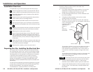
Cabling
For each SCP to be connected to a system switcher, set the rear
panel DIP switches, then follow these steps:
1. If it hasn’t already been done when the wall box was
installed, cut a length of Extron Comm-Link cable to go
between the switcher and the SCP.
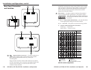
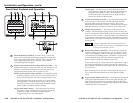
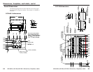
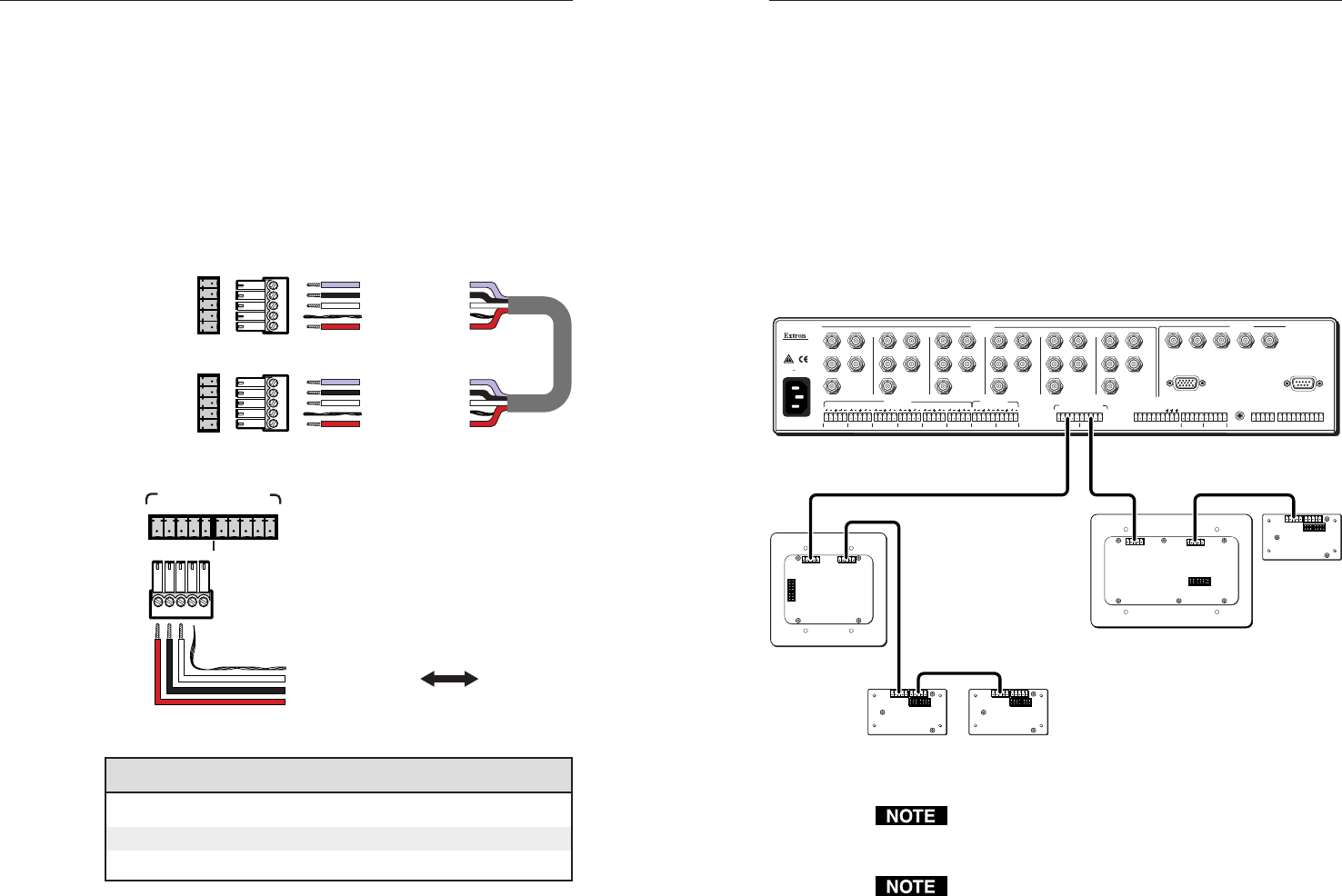
2. Using the diagrams below as a guide, attach a 3.5 mm,
5-pole captive screw connector to each end of the cable.
Wire both ends of the cable identically (pin A to pin A,
pin B to pin B, etc.).
IR signals in (violet)
Gnd (black)
Gnd (drain)
+12V (red)
System 5
AUX port
AUX
A
B
C
D
E
A
B
C
D
E
Comm signal (white)
IR signals in (violet)
Gnd (black)
Gnd (drain)
+12V (red)
Comm signal (white)
Port on
SCP
circuit
board
Wiring for use with a System 5cr Plus switcher
12
SCP/AAP CONTROL
EDCBA
To / from
SCP 200,
SCP 250,
or SCP/AAP A
EDCBA
E
D
C
B
A
Ground (shield/drain)
Ground (black)
Comm. signal (white)
+12VDC (red)
Wiring for use with a System 7SC switcher
Conductor gauges in Extron Comm-Link cables
red and black single strands 18 AWG
white and violet shielded single strands 22 AWG
drain wire 24 AWG
Connectors are included with each SCP, but the cable must
be purchased separately. See page A-4 for cable part
numbers. The cable should not exceed 300 feet
(91.4 meters) in length.
2-72-6
3. Plug one end of the cable into one of the SCP’s
communications connectors, and plug the other end into
the switcher (System 5cr Plus or System 7SC).
4. If you are using a System 7SC switcher, cut a cable and
attach connectors to it for each additional SCP that will be
connected in a daisy chain. Up to a total of 16 SCPs in any
combination of models can be daisy chained together and
connected to the System 7SC.
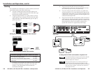
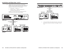
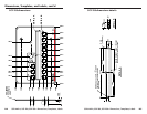
5. Plug one end of the cable into the SCP’s other communica-
tions connector, and plug the other end into a communica-
tions connector on the next SCP closer to the switcher. The
illustration below shows several SCPs connected to a
System 7SC switcher in a typical daisy chain setup.
RS-232
PROJ CONTROL
CONTACT CLOSURE
RELAY 1 RELAY 2
12
DISPLAY PWR
SENSOR
IR COMM
RGB
H/HV
V
INPUTS
AUDIO IN
SCP/AAP CONTROL
OUTPUTS
RGB
Anaheim, CA
100
-
240
50/60 Hz
1.3A MAX.
1
LR
1
LR
2
LR
3
LR
4
LR
5
LR
6
LR
12345
ABCDEABCDE
67
EDCBA ABCDEFGHIJ
FIXED VARIABLE
EDCBAEDCBA
R
R-Y
G/Y
VID
H/HV
V
B/C
B-Y
R
R-Y
G/Y
VID
H/HV
V
B/C
B-Y
R
R-Y
G/Y
VID
H/HV
V
B/C
B-Y
R
R-Y
G/Y
VID
H/HV
V
B/C
B-Y
R
R-Y
G/Y
VID
H/HV
V
B/C
B-Y
R
R-Y
G/Y
VID
H/HV
V
B/C
B-Y
2 3 4 5 6
LR
AUDIO OUT
System 7SC
Rear Panel
SCP/AAP A
SW1
J3J2
1
SCP/AAP A
SW1
J3J2
1
SCP/AAP A
SW1
J3J2
1
SCP 200
SW13
J1J2
11
8
7
6
5
4
3
2
1
SW13
J2
J1
1
1
87654321
SCP 250
A daisy chain of SCPs connected to a System 7SC
The maximum distance away from the switcher that the
last SCP (or other device) in the daisy chain can be
placed is 300 feet (91.4 meters).
Each port of the System 7SC switcher provides up to
12VDC for powering the SCP control pads or other
devices. However, the total load for both ports combined
must not exceed 1 ampere. Each SCP uses 12VDC at
0.06 ampere (60 mA).