


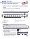

6. Enable auto-input switching (optional). Use a jumper wire to connect pins 4 and 5 of the shared 5-pole captive screw
plug. Attach the plug to the remote connector (
e
on the rear panel diagram on the previous page) if this was not done in
step 5 for the RS-232 connection (see gure 2).
0.3A MAX
POWER
12V
1
2
3
4
INPUTS
OUTPUT
Tx Rx
RS-232 AUTO
REMOTE
1 2 3 4 G
CONTACT
1 2 3 4
+v
TALLY OUT
Figure 2. Enabling Auto-input Switching
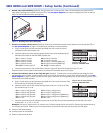
7. Connect a contact closure device (optional). Connect a push-button contact closure device to the Contact port (
d
on
the rear panel diagram on page 1) to enable input switching via contact closure.
a. Plug a 5-pole captive screw connector (provided) into one or both of the two
connectors of the dual Contact port.
b. Insert the signal wire of the contact closure device into the slot representing the
desired input number on the SW HDMI Contact port.
Pin 1 = Input 1 contact
Pin 2 = Input 2 contact
Pin 3 = Input 3 contact
Pin 4 = Input 4 contact
Pin 5 (G) = Contact ground
Pin 6 = Input 5 contact
Pin 7 = Input 6 contact
Pin 8 = Input 7 contact (SW8 only)
Pin 9 = Input 8 contact (SW8 only)
Pin 10 (G) = Contact ground
c. Insert the ground wire of the contact device into the G (ground) slot of the Contact port (pin 5 or 10).
Press the button on the contact closure device to switch the connected input to the output.
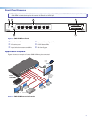
8. Connect an indicator device to the Tally Out port (optional). To identify the currently selected input when the front
panel buttons are not visible, connect a device such as an LED to the input and +V pins of the Tally Out port (
f
on the rear
panel diagram on page 1). When the input you are using is selected, the corresponding tally out pin shorts to ground, which
activates the connected indicator.
a. Plug a 5-pole captive screw connector (provided) into one or both of the two Tally
Out connectors of the dual Tally Out port.
b. Insert the power wire for the contact indicator device into the +V slot of the Tally
Out connector (pin 5 or 10).
Pin 1 = Input 1 tally ground
Pin 2 = Input 2 tally ground
Pin 3 = Input 3 tally ground
Pin 4 = Input 4 tally ground
Pin 5 = +5 V
Pin 6 = Input 5 tally ground
Pin 7 = Input 6 tally ground
Pin 8 = Input 7 tally ground (SW8 only)
Pin 9 = Input 8 tally ground (SW8 only)
Pin 10 = +5 V
c. Insert the ground wire for the indicator into the slot on the Tally Out port that represents the input that you want to
monitor (pin 1, 2, 3, 4, 6, 7, 8, or 9).
Example: One way to use this port is to connect it to a contact closure device with an LED. Connect the contact device to
the Contact port as well. When you use the contact device to switch the input that you are using, the LED lights.
9. Power on the output display.
10. Connect power to the switcher.
11. Power on the source devices.
REMOTE
TALLY OUT
CONTACT RS-232 AUTO
1234+V 5678+V
1234G567 8G Tx Rx
Contact Port for Input
Selection: SW6/SW8 HDMI
REMOTE
TALLY OUT
CONTACT RS-232 AUTO
1234+V 5678+V
1234G567 8G Tx Rx
Tally Out Port for Input Selection
Indication: SW6/SW8 HDMI
SW6 HDMI and SW8 HDMI • Setup Guide (Continued)
2