


Audio/Video Switchers • Installation
Audio/Video Switchers • Installation
Installation, cont’d
2-3
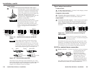
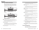
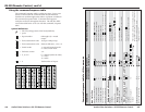
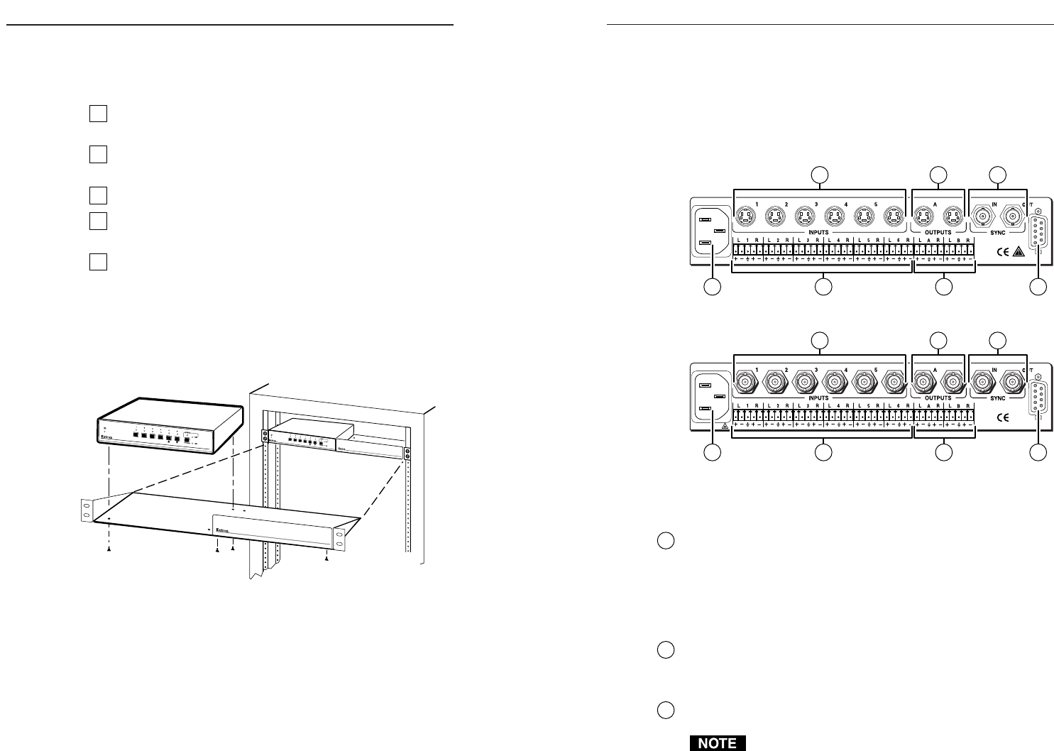
Rear Panel Cabling
All connectors are on the rear panel. Depending on the model
of the switcher, the type and layout of the connectors on the rear
panel will vary. Figure 2-2 shows the rear panel of the
SW6 SV A MX switcher. Figure 2-3 shows the rear panel of the
SW6 AV MX switcher. These two models have all the
connectors available on the A/V switchers.
100-240VAC 50/60Hz
900 mA MAX
1
REMOTE
75
2 4 6
3
Figure 2-2 — SW6 SV A MX rear panel cabling
100-240VAC 50/60Hz
900 mA MAX
1
REMOTE
753
4 62
Figure 2-3 — SW6 AV MX rear panel cabling
Power connection
1
AC power connector — Plug a standard IEC power cord into
this connector to connect the switcher to a 100 to 240VAC, 50 Hz
or 60 Hz power source.
Signal input connections
S-video models
2
S-video input connectors — Connect S-video sources to these
4-pin mini DIN connectors.
Composite video models
2
Composite video input connectors — Connect composite video
sources to these female BNC connectors.
The A/V switchers do not alter the video signal in any
way. The signal output from the switcher is in the same
format as the input.
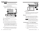
Installation
Installation Overview
To install and set up an Extron A/V switcher for operation,
follow these steps:
1
Turn off all of the equipment that will be connected to the
switcher.
2
Mount the switcher. See Mounting the switcher in this
chapter.
3
Attach the cables. See Rear Panel Cabling in this chapter.
4
Connect power cords and turn on the display devices and
the input devices.
5
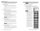
Set the audio gain and attenuation. See Front Panel
Controls and Indicators in chapter 3.
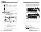
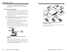
Mounting the switcher
1. For optional rack mounting, mount the A/V switcher on
the left or right side of a 19" 1U Universal Rack Shelf
(Extron part #60-190-01) (figure 2-1).
4-40 X 1/8 Screws
Use 2 Mounting Holes
on Opposite Corners
False Front Panel
Uses 2 Front Holes Only
S
W
6
S
V
A
M
X
A
U
T
O
S
-
V
I
D
E
O
A
N
D
A
U
D
I
O
S
W
I
T
C
H
E
R
S
W
6
S
V
A
M
X
A
U
T
O
S
-
V
I
D
E
O
A
N
D
A
U
D
I
O
S
W
I
T
C
H
E
R
Figure 2-1 — Rack mounting the switcher
a. If feet were previously installed on the bottom of the
case, remove them.
b. Mount the switcher on the rack shelf, using two
4-40 x 1/8 screws in opposite (diagonal) corners to
secure the case to the shelf.
2. If desired, attach a false front panel, or a second ½-rack-
width device to the other side of the shelf.
3. Attach the rack shelf to the rack using four 10-32 x ¾” bolts
and four #10 beveled dress washers.
2-2