


Audio/Video Switchers • RS-232/Remote Control
Audio/Video Switchers • RS-232/Remote Control
RS-232/Remote Control, cont’d
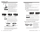
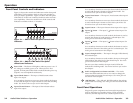
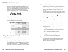
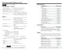
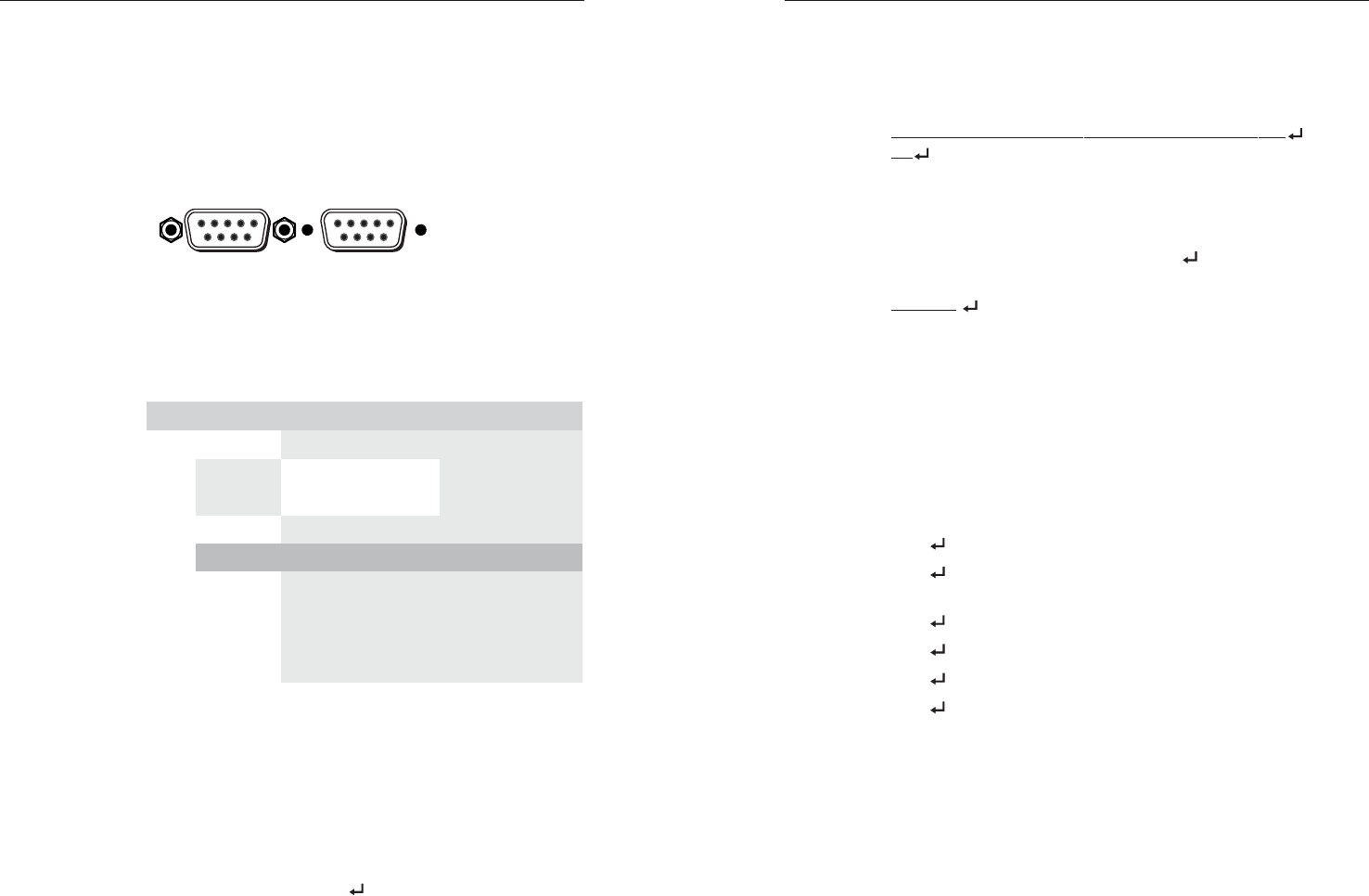
The A/V switchers’ rear panel Remote connectors (Figure 4-1)
can be connected to the serial port output of a host device, such
as a computer or control system, to an Extron IR 20 Universal
SYS 4/8/10/AV remote control, or to a remote contact closure
device. Other than the IR 20, remote communications with the
switcher are via Extron’s Simple Instruction Set, Extron’s
Windows-based control program, or pin-programmed in the
case of a contact closure device.
Female
51
96
Male
15
69
Figure 4-1 — Remote connector pinout
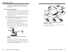
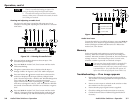
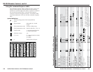
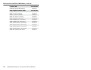
The RS-232 protocol of the rear panel RS-232/Remote connector
is 9600 baud, 1 stop bit, no parity, and no flow control. The
connector has the following pin assignments:
niP 232-SR erusolctcatnoC noitcnuF
1—
1#nI 1#tupnI
2
XT— )-(atadtimsnarT
3
XR— )+(atadevieceR
4—
2#nI 2#tupnI
5
dnG dnG dnuorglangiS
6—
3#nI 3#tupnI
7—
4#nI 4#tupnI
8—
5#nI 5#tupnI
9—
6#nI 6#tupnI
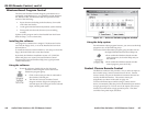
Simple Instruction Set Control
Host-to-interface communications
SIS commands consist of one or more characters per field. No
special characters are required to begin or end a command
character sequence. When a command is valid, the switcher
executes the command and sends a response to the host device.
All responses from the switcher to the host end with a carriage
return and a line feed (CR/LF = ), which signals the end of
the response character string. A string is one or more characters.
Switcher-initiated messages
When a local event, such as a front panel operation or error
condition, occurs, the switcher responds by sending a message
to the host. The switcher-initiated messages are listed below:
(C) Copyright 1996, Extron Electronics AV Series, Vx.xx
Cn
The switcher issues the copyright message and input selected
message when it first powers on. Vx.xx is the firmware version
number. Cn identifies the currently selected input, where n is
the input number (input 1 is the power-up default in normal
mode). The switcher also sends the Cn message whenever
the selected input is changed using the front panel buttons.
Reconfig
The switcher initiates this message when there is a change in an
audio model’s audio gain setting.
Error responses
When the switcher receives a valid SIS command, it executes the
command and sends a response to the host device. If the
switcher is unable to execute the command because the
command is invalid or it contains invalid parameters, the
switcher returns an error response to the host. The error
response codes are:
E01
- Invalid input channel number (out of range)
E06
- Invalid input channel change (auto-switch mode
active)
E09
- Invalid function (mode) parameter
E10
- Invalid command
E13
- Invalid value (out of range)
E14
Illegal command for this configuration
Timeout
Pauses of 10 seconds or longer between command ASCII
characters result in a timeout. The command operation is
aborted with no other indication.
4-34-2