


SW VGArs / Ars Series Switchers • Installation
SW VGArs / Ars Series Switchers • Installation
Installation, cont’d
2-72-6
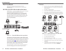
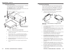
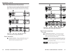
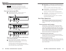
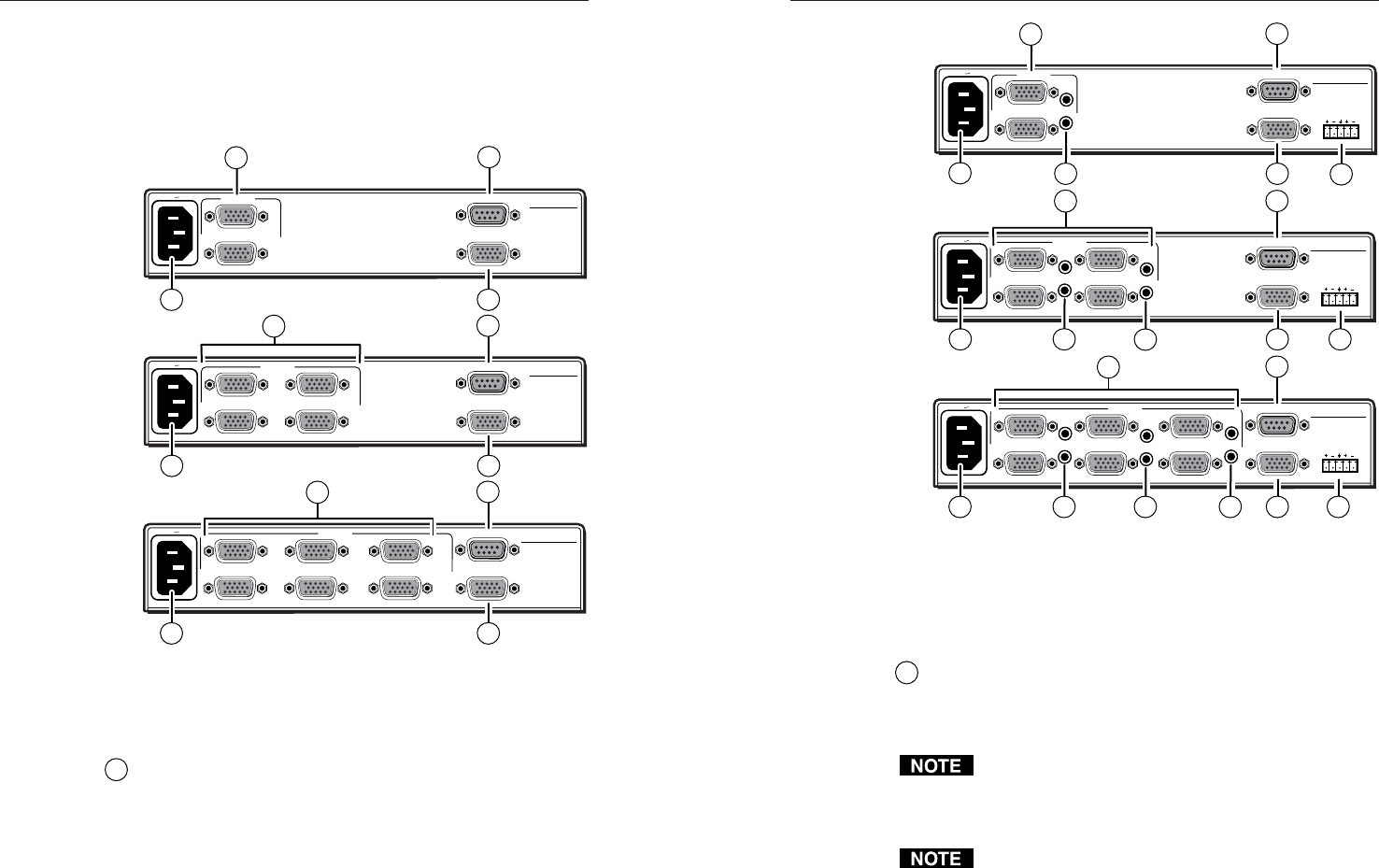
Rear Panel Features and Connections
All connectors are on the rear panel. Depending on the model of
the switcher, the number of connectors on the rear panel varies.
Figure 2-3 shows the rear panels of the SW VGArs switchers.
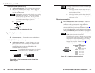
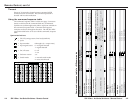
Figure 2-4 shows the rear panels of the SW VGA Ars switchers.
SW6 VGA Ars
REMOTE
100-240V 0.2A
INPUTS
1
2
50-60Hz
OUTPUT
SW2 VGArs
SW6 VGA Ars
REMOTE
100-240V 0.2A
INPUTS
1
2
3
4
50-60Hz
OUTPUT
SW4 VGArs
SW6 VGA Ars
REMOTE
100-240V 0.2A
INPUTS
1
2
3
4
5
50-60Hz
OUTPUT
SW6 VGArs
6
4
6
2
2
2
4
6
4
6
1
1
1
Figure 2-3 — Rear panel - SW VGArs switchers
(no audio input or output connectors)
Power connection
1
AC power connector — Plug a standard IEC power cord
into this connector to connect the switcher to a 100 to
240 VAC, 50 Hz or 60 Hz power source.
SW6 VGA Ars
REMOTE
100-240V 0.2A
INPUTS
1
2
50-60Hz
OUTPUT
OUTPUT
LR
SW2 VGA Ars
SW6 VGA Ars
REMOTE
100-240V 0.2A
INPUTS
1
2
3
4
50-60Hz
OUTPUT
OUTPUT
LR
SW4 VGA Ars
SW6 VGA Ars
REMOTE
100-240V 0.2A
INPUTS
1
2
3
4
5
50-60Hz
OUTPUT
OUTPUT
LR
SW6 VGA Ars
6
2
2
2
4
6
4
6
6
4 5
5
5
3
3
3
3 3 3
1
1
1
Figure 2-4 — Rear panel - SW VGA Ars switchers
(with audio input and output connectors)
Signal input connections
All models
2
Computer input connectors — Connect the computer
inputs (VGA, SVGA, XGA, SXGA, or UXGA) to these
female, 15-pin HD connectors. The number of available
inputs varies with the switcher model.
These input connectors are also compatible with Extron
VSW I AAP VGA video and audio input modules with
the Show Me control button. Refer to the VSW I AAP
user’s manual for details.
The switcher routes the ID bits, pins 4, 11, 12, and 15,
from input 1 only to the output.