


2
68-2296-01 A
02 14
Extron Headquarters
+1.800.633.9876 (Inside USA/Canada Only)
Extron USA - West Extron USA - East
+1.714.491.1500 +1.919.850.1000
+1.714.491.1517 FAX +1.919.850.1001 FAX
Extron Europe
+800.3987.6673
(Inside Europe Only)
+31.33.453.4040
+31.33.453.4050 FAX
Extron Asia
+65.6383.4400
+65.6383.4664 FAX
Extron Japan
+81.3.3511.7655
+81.3.3511.7656 FAX
Extron China
+86.21.3760.1568
+86.21.3760.1566 FAX
Extron Middle East
+971.4.299.1800
+971.4.299.1880 FAX
Extron Korea
+82.2.3444.1571
+82.2.3444.1575 FAX
Extron India
1800.3070.3777
Inside India Only
+91.80.3055.3777
+91.80.3055.3737 FAX
© 2014 Extron Electronics All rights reserved. www.extron.com
GMK-1 • Setup Guide (Continued)
Mounting the SMB 1 on the GMK 1
6. Align the four holes on the back of the SMB 1 with the
four studs on the GMK 1. Secure the SMB 1 to the
GMK1 using the four provided nuts. Do not overtighten
the nuts.
ATTENTION: The SMB 1 must be mounted so
that the touchpanel faces upwards and the
cutout for the cable is at the bottom.
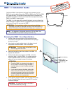
Installing the Touchpanel in the SMB 1
7. Secure the wall plate adapter to the SMB 1, using the four provided
screws.
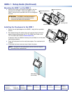
8. Run cables through the cable cutout and connect them to the back
panel of the touchpanel (see the TLP Pro 320M User Guide or the
TLPPro 520M User Guide at www.extron.com).
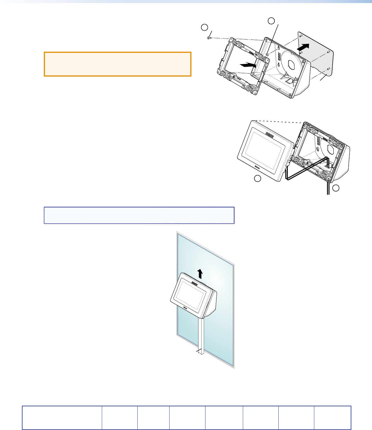
If required, mount an adhesive raceway (not provided) to run the cable
(see the gure below).
9. Press the touchpanel onto the wall plate adapter. Four catches hold it
in place.
10. If the bezel has been removed, snap it back into place.
NOTE: The bezel for the touchpanels can be removed using the
provided Extron removal tool.
Cable Racewa
y
(not included)
UP
TLP Pro 520M
9
8
Mounting Nuts (4)
Wall Plate Adapter
SMB 1
GMK 1
Mounting Plate
Mounting Screws (4)
6
7