


1 VSC 50 Scan Converter • Setup VSC 50 Scan Converter • Controls and Indicators
Setup
3
Controls and Indicators
2VSC 50 Scan Converter • Setup
The Extron VSC 50 converts computer scan rates of up to 800 x 600 to
NTSC/PAL and S-video outputs. The scan converter connects between
the computer and the desired output devices (monitor, VCR, or any
compatible video device).
Setting up the VSC 50
To install and set up the VSC 50, follow these steps:
1
Turn off all of the equipment. Ensure that the computer video
source and the output devices are all turned off and disconnected
from the power source.
2
Attach the cables. See “Rear panel cabling” below.
3
Set the rear panel DIP switches. See “Rear panel switch settings”
on page 2.
4
Connect power cords and turn on the displays and the computer,
in that order.
5
Make picture adjustments with the controls on the front panel.
See “Front Panel Controls and Indicators” on page 3.
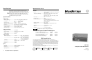
Rear panel cabling
All connectors are on the rear panel. Figure 1 and figure 2 show the
cable connections on the rear panel of the VSC 50.
Input connections
1
PC or Macintosh connection — Use the 6-foot VGA/Mac adapter
cable (part #26-462-01) provided for connecting the VSC 50 to
either a PC type or a Macintosh computer. The connector size and
gender prevent making improper connections.
PC connections — Plug the VGA end of the Mac/VGA
adapter cable into the computer’s video card output
connector and plug the Mac end into the Mac connector on
the VSC 50 rear panel (figure 1). Plug the monitor's video
cable into the VGA connector on the rear panel of the VSC 50.
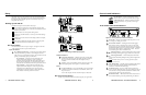
Mac connections — Plug the Mac end of the Mac/VGA
adapter cable into the computer’s video output connector
and plug the VGA end into the VGA connector on the
VSC 50 (figure 2). Plug the monitor’s video cable into the
Mac connector on the rear panel of the VSC 50.
PC computer
LISTED
1T23
I.T.E
C
/
INPUT/LOOP OUT
VCR
(composite video)
1 2 34
Videoconference
system (S-video)
Figure 1 — Connecting a PC type computer
Macintosh computer
LISTED
1T23
I.T.E
C
/
INPUT/LOOP OUT
VCR
(composite video)
Videoconference
system (S-video)
24 31
Figure 2 — Connecting a Macintosh computer
Output connections
2
Composite (NTSC/PAL) — This BNC connector provides either
NTSC or PAL composite video, depending upon the position of
the rear panel PAL Out DIP switch. This output is always
available.
3
S-video — This 4-pin mini-DIN connector outputs S-video. This
is the highest quality video output for a VCR or a CODEC.
Power
4
AC power connector — Plug a standard IEC power cord into this
connector to connect the VSC 50 to a 100 to 240VAC, 50 Hz or 60
Hz power source.
Turn on the computer monitor and the computer, in that order.
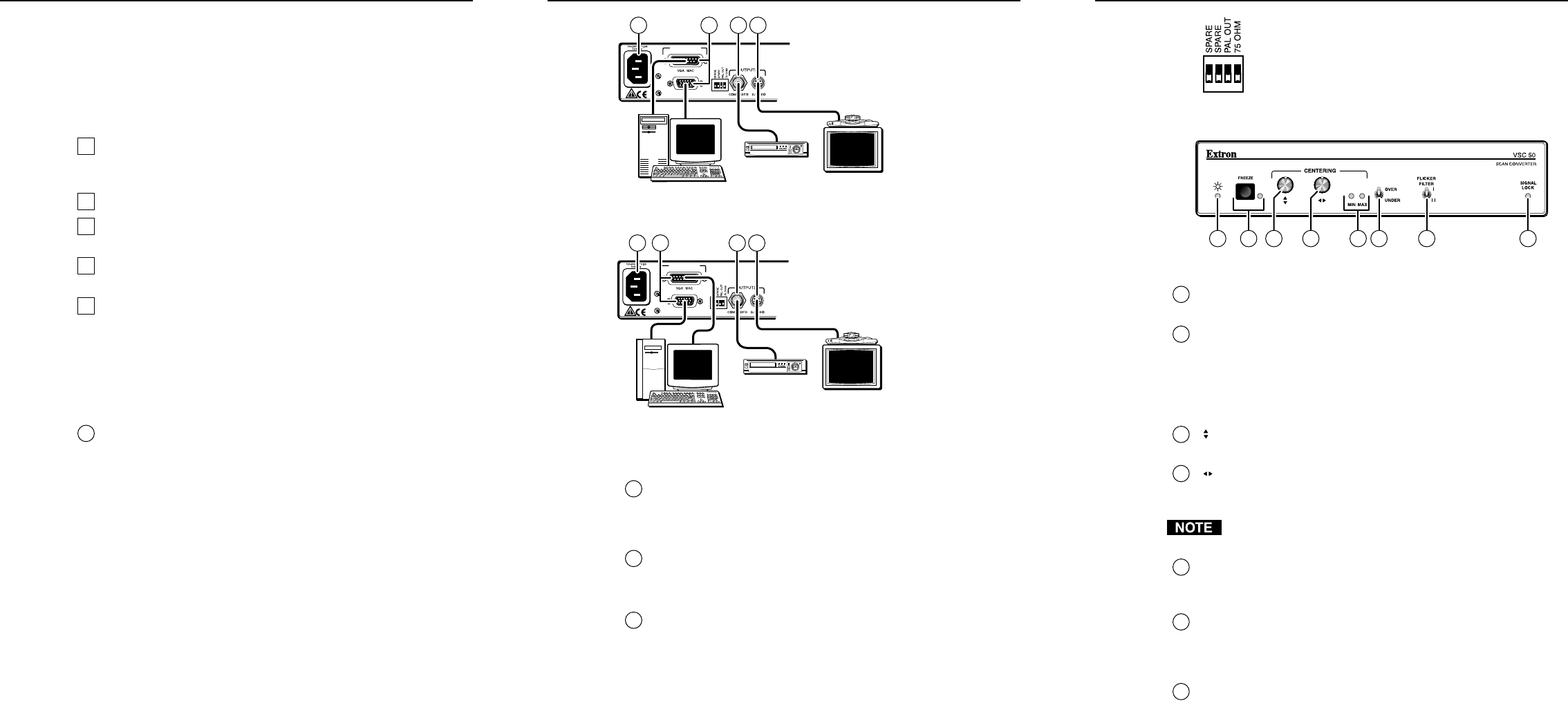
Rear panel switch settings
Set the rear panel DIP switches as needed to support your application:
PAL Out switch — Set this switch down for NTSC
(525 line video) or up for PAL (625 line video) output.
75 Ohm DIP switch — Set this switch down (Hi Z) if
using a local monitor, or up (75 ohm) if not using a
monitor.
Front Panel Controls & Indicators
5 10 11 126 7 8 9
Figure 3 — Front panel controls and indicators
5
Power LED — The Power LED lights to indicate power is on. If
AC voltage is available, power is on.
6
Freeze button and LED — Pushing the Freeze button toggles
between freeze frame or motion mode. Freeze provides a still
image capture of a scan-converted computer screen. The Freeze
LED indicates that the VSC 50 is in freeze frame mode. While this
LED is lit, the video output is a single frame of video. Press the
freeze button again to return to motion mode.
7
Centering (vertical) — This knob adjusts the vertical position
(vertical shift), by shifting the image up and down on the screen.
8
Centering (horizontal) — This knob adjusts the horizontal
position (horizontal shift), shifting the image left and right on the
screen.
Nonvolatile memory saves the centering adjustments for the
current scan rate.
9
Min and Max LEDs — The Min or Max LED lights to indicate the
vertical or horizontal centering adjustment has reached the
minimum or maximum limit of its range.
10
Over/Under switch — The Over/Under switch provides two
ways to view the displayed image: the Over position provides an
overscan that is 10% larger than the standard size and the Under
position displays the image at its normal size.
11
Flicker Filter switch — The Flicker Filter switch selects from two
levels of flicker filtering. Select the position that gives the best