


Installation
The Extron VSS 100 composite video sync separator extracts the sync
signal from an RGsB, component video, S-video, or composite video
input. The sync separator outputs the composite sync signal, at TTL
levels, on a separate signal line. The VSS 100 loops the input video
through and outputs it unchanged.
With the VSS 100, systems that use video formats with embedded sync
in the video stream can still take advantage of features that depend on a
separate sync input, such as the DSVP™ (Digital Sync Validation
Processing™) feature of Extron CrossPoint Plus matrix switchers.
The VSS 100 accepts input video on a female BNC connector. The video
input should be the signal that has the sync signal embedded on it, such
as the luminance (Y) signal for S-video.
1
2
34
5
6
7
8
91
0
1
1
1
2
1
2
3
4
5
6
7
8
Extron
CrossPoint Plus 128HVA
Projector
Extron
VSS 100
V
S
S
1
0
0
DVD Player w/
S-video Output
S-video
Y (Luma) Signal
C (Chroma)
Signal
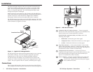
Figure 1 — Typical VSS 100 application
The VSS 100 loops the video input through and outputs it on a separate
female BNC connector. The sync separator outputs the separated
composite sync, at TTL levels, on a third female BNC connector.
The VSS 100 easily fits behind a rack mounted Extron switcher, and
includes a 6” male-to-male BNC cable for easy integration into a video
system. The sync separator has an external, worldwide power supply.
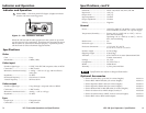
Connections
The CV Input and Loop-thru connectors are on the front of the VSS 100.
The Composite Sync Out and power connectors are on the back (figure 2).
VSS 100
LOOP-
THRU
CV-INPUT
POWER
9-24V
0.35A MAX.
C-SYNC
OUT
1 2
3
4
Figure 2 — VSS 100 connectors
1
Composite video (CV) Input connector — Connect composite
video (or the video input that has composite sync embedded in it)
from the video source to this female BNC connector.
For RGsB video, component video, or S-video, connect the
following video signal:
• RGsB video: Connect the green video signal
• Component video: Connect the luminance (Y) video signal
• S-video: Connect the luminance (Y) video signal
2
Loop-Thru connector — Connect the included 6” male-to-male
cable to this female BNC connector. Connect the other end of the
cable to the desired destination (such as the green video input of a
CrossPoint Plus matrix switcher for RGsB video).
3
Composite Sync Out connector — Connect the TTL-level
composite sync signal output on this female BNC connector to the
device that needs the sync signal (such as the horizontal sync
input of a CrossPoint Plus matrix switcher).
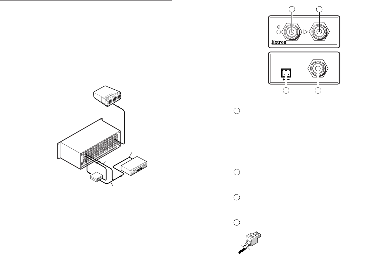
4
Power connector — Plug the external 12VDC power supply into
this captive screw connector. Wire the connector as
shown at left. Plug the other end of the power supply
into a standard AC outlet.
Return
+12V
1 VSS 100 Sync Separator • Introduction 2VSS 100 Sync Separator • Connections