


2
68-1798-01 Rev. C
02 13
Extron Headquarters
+1.800.633.9876 (Inside USA/Canada Only)
Extron USA - West Extron USA - East
+1.714.491.1500 +1.919.850.1000
+1.714.491.1517 FAX +1.919.850.1001 FAX
Extron Europe
+800.3987.6673
(Inside Europe Only)
+31.33.453.4040
+31.33.453.4050 FAX
Extron Asia
+65.6383.4400
+65.6383.4664 FAX
Extron Japan
+81.3.3511.7655
+81.3.3511.7656 FAX
Extron China
+86.21.3760.1568
+86.21.3760.1566 FAX
Extron Middle East
+971.4.299.1800
+971.4.299.1880 FAX
Extron Korea
+82.2.3444.1571
+82.2.3444.1575 FAX
Extron India
1800.3070.3777
Inside India Only
+91.80.3055.3777
+91.80.3055.3737 FAX
© 2013 Extron Electronics All rights reserved. www.extron.com
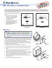
WPC 160 A Series • Installation Guide (Continued)
VGA and TRS Connections
HD‑15 Pin TRS Captive Screw Pin Color
1 Red* R Red coax
2 Green* G Green coax
3 Blue* B Blue coax
4 ID Bit 2 N/A Green (not used)
5 Ground
(right block) Violet
6 Red Gnd* Rg Red coax shield
7 Green Gnd* Gg Green coax shield
8 Blue Gnd* Bg Blue coax shield
9 DDC +5 V*
(see note at right)
+5 Gray
10 Sync Gnd*
(main block) Black (red/black pair)
11 ID Bit 0 N/A Blue (not used)
12 ID Bit 1 or DDC D Yellow
13 H sync* H Red (red/black pair)
14 V sync* V White (white/black pair)
15 ID Bit 3 or Clock C Black (white /black pair)
* Tip Audio T (Left) Orange
* Ring Audio R (Right) Brown
* Sleeve Audio S (Ground) Shield
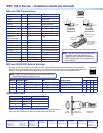
DDC and ID Bit DIP Switch Settings
The table at left below shows the function of the DIP switches. The table at right below shows how the switches
affect the monitors supported and some of the more common ID bit settings. Check the manual supplied with your
display to see if ID bit termination is required by your AV system. If you are unsure, set all switches to off.
NOTE: If DDC is to be used, switches 1 and 3 must be set to on
and switches 2 and 4 must be set to off.
1 2 3
4
ON
DIP Switches
Display Used
DIP Switch
1 2 3 4
No ID bit required Off Off Off Off
Monochrome monitor (not XGA) On Off Off Off
Color monitor (not XGA) Off On Off Off
Color monitor (supports XGA) Off On On Off
Switch ID Bit Pin Off On
1 ID 0 HD-15 pin 11 open HD-15 pin 11 to ground
2 ID 1 HD-15 pin 12 pass-thru HD-15 pin 12 to ground
3 ID 2 HD-15 pin 4 open HD-15 pin 4 to ground
4 ID 3 HD-15 pin 15 pass-thru HD-15 pin 15 to ground
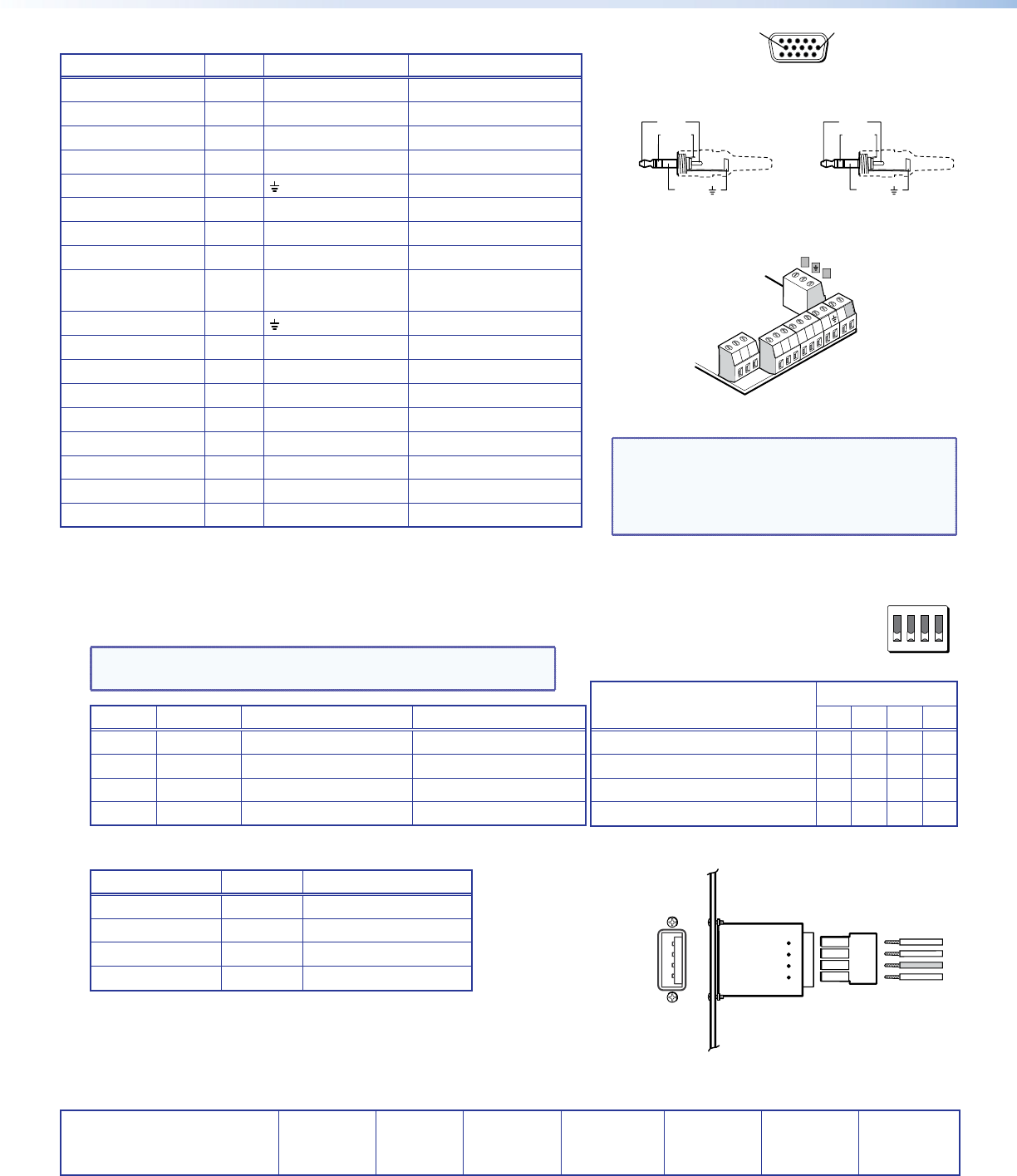
USB Connections
USB Connector Signal Captive Screw Pin
1 +5 V (bus) 1
2 Data + 2
3 Data - 3
4 Ground 4
Wire the 4-pole captive screw connector (provided) as shown in the gure at
right. Insert the connector into the slots on the back of the WPC 160.
51
15 11
610
Female HD-15
Pin Locations
Sleeve ( )
Ring (
-
)
Tip (+)
3.5 mm Stereo
Plug Connector
(balanced audio)
Sleeve ( )
Ring (R)
Tip (L)
3.5 mm Stereo
Plug Connector
(unbalanced audio)
Captive Screw
Connectors
D
C
*
*
*
*
*
*
*
*
*
*
Connectors labeled in
gray are optional.
*
*
*
*
*
R GgRg
G BgB
H V
+5
+5
T SR
Labels for captive
screws match HD-15
pins, as shown in
the table at left.
*Cut these wires 1 inch shorter. See the table at left.
NOTE: VGA pin 9 may be used to detect DDC
availability. Check the manual for your
display to see if this feature is required for
DDC communication. If you are unsure, do
not use the pin.
1
2
3
4
1
2
34
USB
Connector
Captive Screw
Connector
WPC 160 A
USB Connector