© 2007 Fairchild Semiconductor Page 5 of 17 Rev 1.1 April 2007
www.fairchildsemi.com
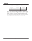
Table 1: Jumper JP1/JP2 Status and LED Current
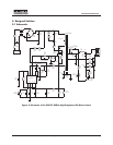
Refer to the schematic in Figure 3. As the LED current returns back to the power supply, it develops a
voltage across the sense resistor(s). Once this voltage reaches the base-emitter junction voltage of the
NPN Q2, typically about 650mV, the transistor will conduct collector current. This current also flows
through the photodiode inside the optocoupler, IC2. The optocoupler will transfer this feedback
information optically across the primary-secondary boundary to the primary side of the supply
thereby maintaining the necessary isolation. Thermistor RTH1, is a negative temperature coefficient
device and compensates for changes in base-emitter voltage due to temperature change.
LED Current JP1 Status JP2 Status
350mA Out Out
700mA In Out
1A In In


