


July 2000, Rev. A
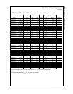
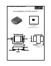
DO-214AB(SMC) Tape and Reel Data, continued
Dimensions are in millimeter
Pkgtype
A0 B0 W D0 D1 E1 E2 F P1 P0 K0 T Wc Tc
6.00
+/-0.15
8.25
+/-0.20
16.0
+/-0.3
1.55
+/-0.05
1.125
+/-0.125
1.75
+/-0.10
10.25
min
7.5
+/-0.05
8.0
+/-0.1
4.0
+/-0.1
2.4
+/-0.30
0.40
+/-0.10
13.0
+/-0.3
0.06
+/-0.02
P1
A0
D1
P0
F
W
E1
D0
E2
B0
Tc
Wc
K0
T
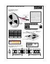
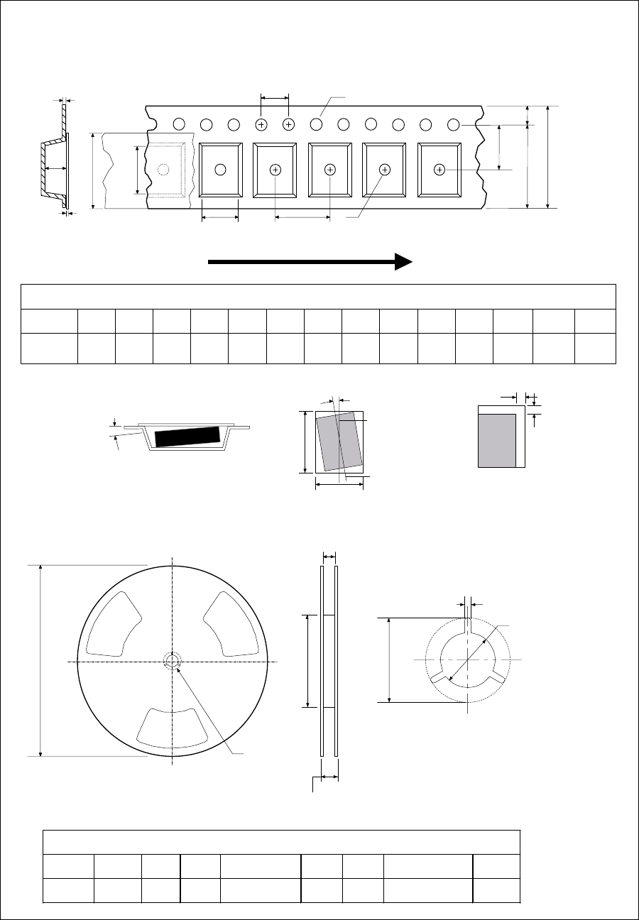
Dimensions are in inches and millimeters
Tape Size
Reel
Option
Dim A Dim B Dim C Dim D Dim N Dim W1 Dim W2
12mm 13" Dia
13.0
330
0.059
1.5
512 +0.020/-0.008
13 +0.5/-0.2
0.795
20.2
1.97
50 min
0.646 +0.078/-0.000
16.4 +2/-0
0.724
18.4
See detail AA
Dim A
max
13" Diameter Option
W2 max Measured at Hub
W1 Measured at Hub
Dim N
Dim D
min
Dim C
B Min
DETAIL AA
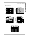
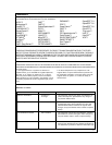
Notes: A0, B0, and K0 dimensions are determined with respect to the EIA/Jedec RS-481
rotational and lateral movement requirements (see sketches A, B, and C).
20 deg maximum component rotation
0.5mm
maximum
0.5mm
maximum
Sketch C (Top View)
Component lateral movement
Typical
component
cavity
center line
20 deg maximum
Typical
component
center line
B0
A0
Sketch B (Top View)
Component Rotation
Sketch A (Side or Front Sectional View)
Component Rotation
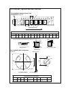
User Direction of Feed
Configuration: Figure 3.0
DO-214AB(SMC)
(12mm)
DO-214AB(SMC) Embossed Carrier Tape
DO-214AB(SMC) Reel Configuration:
Figure 4.0