


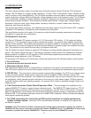
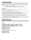
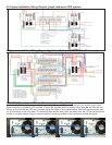
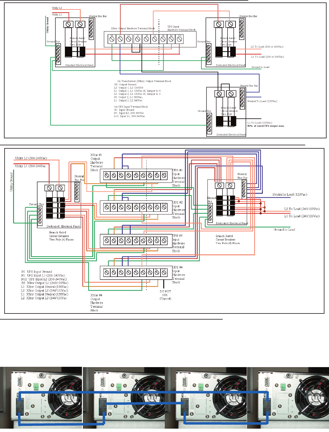
4.8 System Installation Wiring Diagram (single rackmount UPS system)
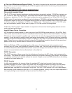
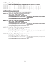
4.9 System Installation Wiring Diagram (typical multiple parallel UPS units, Rackmount)
13
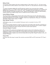
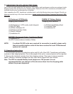
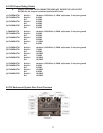
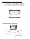
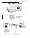
4.10 UPS & Transformer Modules Communications Bus Cabling
Use one UA88385 parallel communications bus cabling kit for each UPS to be connected to the system output trans-
former module or to paralleled UPS systems. Connect the supplied cables as shown below. Note the first and last con-
nectors on the first and last UPS are connected using the longer of the supplied cables. Switch on the termination resis-
tor dip switch next to the long cable. For the transformer module, daisy chain the cables from the UPS to the transformer
module in a similar manner using the communications connectors located on the transformer module rear panel.