


5
1.0 INTRODUCTION
Manual Overview
This user manual has been written to provide basic information about Falcon FN Series -2TXI rackmount
models. The FN Series is a rugged, double conversion, "on-line" UPS. It has galvanic output isolation config-
ured for single or dual voltage output(s). The FN Series provides continuous power conditioning and accepts
a wide range input voltage, while providing tight voltage regulation and a true sinewave output. The FN Series
UPS is specifically designed to protect sensitive computers, laboratory and industrial equipment against the
widest range of power problems. These problems include power failures, voltage sags, voltage surges,
brownouts, utility line noise, high voltage spikes, frequency variations, common mode noise, switching
transients, and harmonic distortion.
This manual also details unpacking, unit installation and the major features of the FN Series UPS, in addition
to detailed UPS operation, configuration and troubleshooting information.
The specifications section at the end of this manual provides detailed operating parameters and general
information on approvals and certifications.
FN Rackmount Overview
The Falcon FN Series UPS system consists of (1) 2U Rackmount UPS module, (1) 3U rackmount battery
module and (1) 2U rackmount output isolation transformer module. An optional input isolation transformer
module is also available. The modules are designed to be easily installed in a standard 19” equipment rack.
The equipment rack must be equipped with hard mounted shelves to properly support the weight of the mod-
ules. The modules do not support the mounting of equipment slide rails.
The FN Series front panel features a graphical LCD display, providing detailed operational information at a
glance. The display enables the user or field service engineer to easily monitor and troubleshoot localized
power problems, in addition to UPS operation. UPS control and programming are easily accessed using
pushbuttons located adjacent to the LCD display.
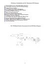
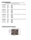
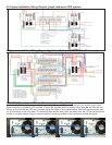
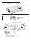
FN rackmount UPS, Battery and Transformer module rear panels have the following features and functions:
a. Circuit Breakers.
b. Hardwire input/output terminal blocks.
c. Maintenance Bypass Switch
The maintenance bypass switch is located behind a protective cover plate on the transformer box rear panel.
The UPS must be placed into manual static bypass mode prior to switching the maintenance bypass switch.
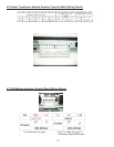
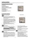
d. RS-232 Port - This port may be used to provide communications between the UPS and a network server
or other computer system. When used in conjunction with the supplied UPSilon software, remote UPS
monitoring and control are facilitated. The software will automatically save all open computer files and initiate
an unattended, orderly operating system shutdown in the event of a utility power outage. UPSilon supports
most MS Windows and Linux operating systems. An optional UNIX version is available through Falcon at an
additional cost.
e. Two Communications Option Board Expansion Slots - The slots support the installation of an
optional SNMP/HTTP Agent or contact closure interface boards. The SNMP/HTTP Agent board is a TCP-IP
addressable solution to remote UPS monitoring and management via LAN, WAN or the Internet. The agent
board is supplied with client software that will remotely shut down multiple servers or computers through the
Ethernet LAN. A CD containing software clients and a SNMP MIB II compliant MIB is provided that supports
most popular operations systems.
f. Two RJ45 connectors for connection of UPS parallel operation or remote maintenance
bypass interface cables.
Used when UPS and transformer modules, or multiple UPS systems are
connected in parallel.
WARNING: Only FN rackmount models of identical power ratings may be connected in parallel. For example, a
FN3KRM-2TXI may only be connected in parallel with another FN3KRM-2TXI unit. The FN5KRM-2TXI may only be
connected in parallel with another FN5KRM-2TXI. The same is true for the FN6KRM-2TXI model.