


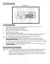
Next Page Button
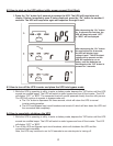
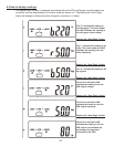
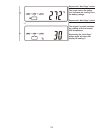
1. When the LCD display is in “Normal Mode”, repeated pressing of this button will sequence down
through the input/output/battery parameters and readings.
2. When the UPS is displaying “OFF” or “BPS”, depressing the “Next Page” and “Function” buttons at the
same time will place the UPS into “Programming Mode”. Refer to the “How to Change the Programmed
Settings” section of this manual for more details.
3. When in “Programming Mode”, repeated pressing of this button will sequentially select the various
programmable parameters. Refer to page 27, “How to Change the Programmed Settings” section of this
manual for more details.
Confirm Button
1. When in “Programming Mode” and prompted on the LCD display to SAVE settings, pressing this button
will save all changed parameters.
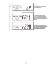
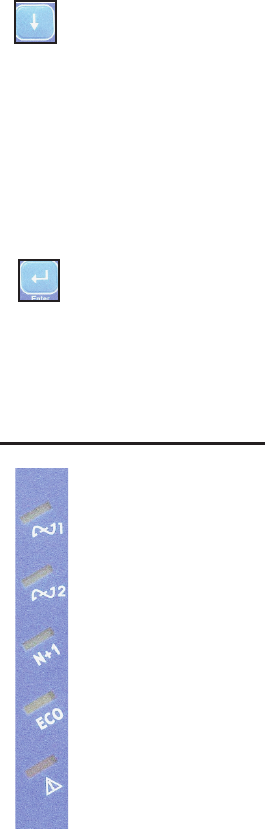
Utility (AC Source 1) UPS Input Power Present LED (Green) -- Indicates utility power is present and the
UPS input circuit breakers is turned on. If the utility voltage is out of tolerance the LED will turn off.
Bypass (AC Source 2) Bypass Input Power Present LED (Green)-- Indicates bypass power is present
and the Bypass circuit breaker is turned on. If bypass power is out of range, the LED will turn off.
N+1 Mode Enabled (Green) - Indicates multiple UPS units are connected in parallel and have been
properly configured and programmed for Parallel N+1 mode operation.
Economy/Green Mode Enabled (Yellow) -- Indicates Economy/Green mode has been enabled.
Alarm Condition Present (Red) -- Indicates the UPS in an alarm condition.
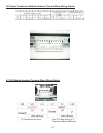
5.3 LED Display Modes
16