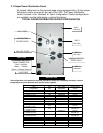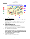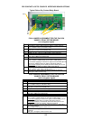
5. BYPASS INDICATOR LED
When this led is lit, the UPS bypass is active. Should the Alarm led be lit at the
same time, the UPS detected an internal failure and the UPS must be serviced.
6. INVERTER INDICATOR LED
When this led is lit, the UPS inverter is operating and powering the connected load.
7. GREEN MODE LED INDICATOR
This led is lit when the connected output load of the UPS drops to under 10% of
the full rated output of the UPS, providing SW3 is in the "down" position (Green
Mode Enabled) as shown on page 7. The UPS is automatically set to bypass mode
and the inverter is turned off, reducing the power requirement. NO BATTERY
BACKUP IS PROVIDED IN THIS MODE. (The UPS is shipped from the factory with
SW3 in the "up" or disabled position.)
8. OVER CREST INDICATOR LED
This led lights up when the connected load is close to the peak current rating of the
UPS.
9. ALARM INDICATOR LED
This led is lit during the following conditions:
a. The inverter voltage is too high or low.
b. UPS over-temperature condition.
c. The battery voltage is too high.
d. The internal DC Bus has an under or over voltage condition.
e. The internal microprocessor or memory failure.
10. ON / OFF BUTTON
The following describes the different modes of operation for this button:
a. Depressing this button when the UPS is off, and the utility voltage is not present,
or with the UPS input circuit breaker in the off position, will cause the UPS to DC
start and run on internal battery momentarily and shutdown.
b. Pressing this button while the UPS is on, and utility is present, will place the UPS
into bypass mode.
c. Pressing this button when the UPS input circuit breaker has been turned off, or
when the utility voltage is not present, will turn off the UPS.
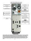
TO TURN UPS ON: CONNECT THE UPS TO UTILITY POWER AND TURN ON THE
BATTERY DISCONNECT CIRCUIT BREAKER FIRST, THEN TURN ON THE MAIN AC
CIRCUIT BREAKER LOCATED ON THE REAR PANEL. DO NOT PRESS THE “ON”
BUTTON LOCATED ON THE FRONT PANEL OR THE UPS WILL BE PLACED INTO
BYPASS MODE.
TO TURN UPS OFF: TURN OFF THE MAIN CIRCUIT BREAKER LOCATED ON THE
REAR PANEL AND DEPRESS THE "ON/OFF" BUTTON UNTIL THE UPS BEEPS AND
WAIT FOR THE UPS TO SHUT DOWN AND TURN OFF (ABOUT 30 SECONDS).
11. TEST BUTTON
The following describes the different modes of operation for this button:
a. Pressing the Test button while in Green Mode will disable Green Mode.
b. Pressing the Test button while utility is present will put the UPS through a self-test
diagnostic.
c. Pressing the Test button while in battery mode will turn the battery Audible alarm
off. Depressing it again will turn the Audible alarm back on.
18


