


16
INSTALLATION PROCEDURE
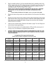
1. Verify the battery disconnect circuit breaker on the UPS and all external battery banks
to be connected are in the off position.
2. Locate the battery interconnect cable(s).
3. Connect one end of the battery interconnect cable to the the UPS battery
connector located on the power distribution center (see page 14). Connect the other
end of the cable to the battery connector on the first battery bank as shown.
4. If a second battery bank is to be connected, connect the second battery interconnect
cable to the lower (second) battery connector on the first battery bank, and the other
end to the upper battery connector of the second battery bank. All subsequent battery
banks will be connected in the same manner.
5. Follow the instructions in the proceeding step for additional battery banks.
6. Turn the battery disconnect circuit breaker to the “on” position for the UPS and all
extended battery banks.
7. For all battery banks having the internal battery charger option installed from the
factory, perform the following:
a. Verify the battery charger circuit breaker is in the off (down) position.
b. On the battery bank nameplate label located on the rear panel, verify the
battery charger input voltage matches your utility source (120Vac or
230Vac).
c. Connect the input line cord(s) to the battery bank(s) power inlet.
d. Plug the other end of the power cord into a utility receptacle.
e. The batteries in the external battery banks are now being charged.
NOTE: Internal battery bank chargers do not charge the batteries inside the UPS.
NOTE: When the battery banks and UPS need to be shut down or stored for more than
two weeks, turn off the battery charger circuit breaker and turn off the UPS
battery circuit breaker, otherwise battery damage may occur due to excessive
discharge.
Please refer to the battery bank selection guide on page 11 for more model details.
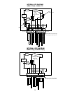
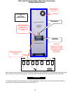
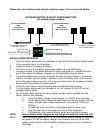
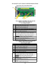
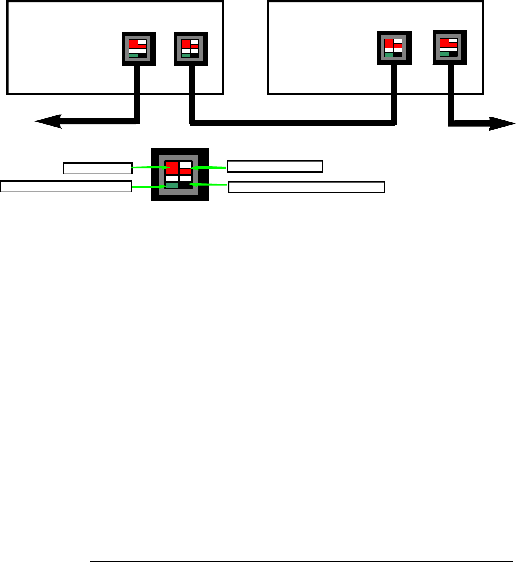
EXTENDED BATTERY BANK DC INTERCONNECTION
(All models except hardwire)
To UPS Battery Connector
(See Step 3 below)
1st Extended Battery
Bank
Connections
(Rear Panel View)
2nd Extended Battery
Bank
Connections
(Rear Panel View)
To the Battery Connector on
the next Battery Bank
To the Battery Connector
on the second Battery Bank
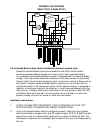
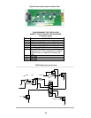
Detailed
View
RED PIN IS +240Vdc
BLACK PIN IS THE 240Vdc Return
RED KEY PIN
GREEN PIN IS Chassis Ground