


Initial Setup
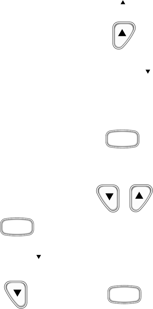
The speedometer is used to initialize the
parameters for each serial bus installation.
Holding the “mode-M” button down while
turning on power will allow access to
these parameters. Pressing and releasing
the “mode-M” button will select one of the
following options:
1. Trim calibration. The display will show
“TRIM” and a down arrow, “ ”. Using the
trim control, set the motor to the lowest
position. Press the “Down” button when
the
engine is at it’s lowest point to store the
value. The display will change to “TRIM”
and an up arrow, “ ”. Trim the engine to
its highest level. Press the up button when
the engine is at it’s highest point to store
the value. The display will go back to
“TRIM” and a down arrow, “ ”. The trim
calibration is now complete. To go to
speedometer selection, press the “mode-
M” button for less than 1 second.
To exit initial set-up, press and hold the
“mode-M” button for more than 1 second.
The trim calibration can be repeated if
desired.
2. Speedometer selection. Pressing and
releasing the “Up” button or the “Down”
button
will change the display to select one of two
speedometers:
• 70 MPH (default)
• 50 MPH
To go back to trim calibration, press the
“mode-M” button for less than 1 second.
To exit initial set-up, press and hold the
“mode-M” button for more than 1 second.
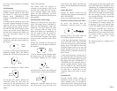
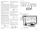
M
Mode
Button
M
Mode
Button
M
Mode
Button
Down
Button
Up
Button
Down
Button
Up
Button
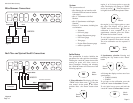
System
The system consists of:
• One Gateway box to interface with
Evinrude ECM and external senders
and sensors.
• One 4” Tachometer with Fuel
Monitor
• One 4” Speedometer with Depth
Sounder
• Various 2” instruments, including but
not limited to
• Voltmeter
• Oil Level gauge
• Engine Temperature gauge
• Fuel Level gauge
• Trim gauge
• Engine Water Pressure gauge
• others as specified.
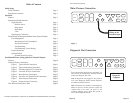
Page 2
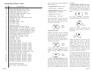
Figure 5
Figure 6
Faria Serial Bus Gateway
Miscellaneous Connections
Fuel Flow and SystemCheck® Connections
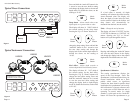
P15
P13
P14
P12 P11
P7
P9
P8P10 P6
P5 P4 P1
P3 P2
Pink/Yellow
Pink
Black
Black White Purple/White
White
Shield w/Heat Shrink
1 2 3
P15
P13
P14
P12
P11
P7
P9
P8P10 P6
P5 P4 P1
P3 P2
5
6
7
White/Tan
Oil
Level
Sender
Trim
Sender
Fuel
Level
Sender
SystemCheck
Connector
HN0524
HN0523
Page 13
Fuel Flow Transducer