


Removal and Replacement Procedures
Maintenance and Service Guide 5–65
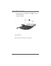
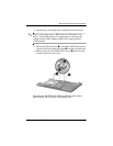
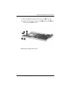
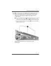
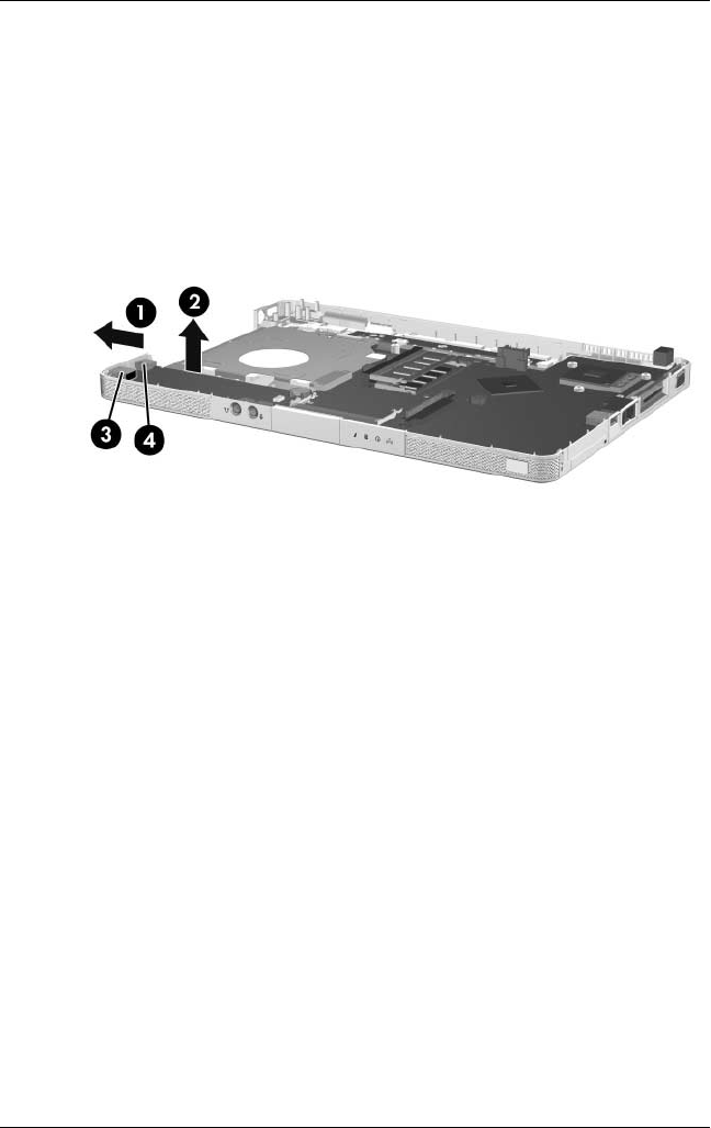
9. Flex and hold the left edge of the top cover 1 to the left.
10. Lift the left side of the system board 2 until the USB 3 and
1394 connectors 4 are clear.
Releasing the System Board, Part 1