


FTLX1341E2 Product Specification – October 2008
© Finisar Corporation – October 2008 Rev B Page 4
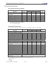
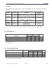
Electrical Pad Layout
Figure 1- X2 Transponder Electrical Pad Layout
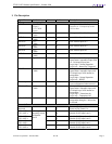
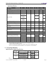
II. Absolute Maximum Ratings
Limit Values
Parameter Symbol
min. max.
Unit
Storage Temperature
1)
T
S
-40 85 °C
Supply Voltage +5.0 V V
5
0 6 V
Supply Voltage +3.3 V V
3
0 4 V
Supply Voltage APS V
aps
0 1.5 V
Static Discharge Voltage, All Pins
2)
ST
d
500 V
Average Receive Optical Power Rx
P
max
1.5 dBm
Notes:
1) Non-condensing
2) HBM
Stresses in excess of the absolute maximum ratings can cause permanent damage to the device.