


IBBI Electronics
6
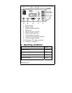
• Put VM/Vout switch [(10)] to Vout position
• Put C/V switch [(8)] to C position
• Amp LED indicator will light up [(4)]
• [(3)] will display “A” for Ampere
• Actual current value will be displayed on [(2)]
with two decimal places
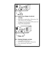
5.4 Voltmeter mode
5.4.1 Measuring voltage at various
positions while powered from the
PS1010-3A
• Set required output voltage and power up the
DUT
• Put VM/Vout switch [(10)] to VM position. VM
LED indicator [(4)] will light up.
• Test voltage values using the VM probe [(11)].
The voltage values are displayed relative to the
GND pin of the Vout terminal [(9)].
Note: the user can select various switch positions at
any time to see the Current limit, Actual current
flow, voltage at output terminals or at VM without
disrupting the power at the output terminals.