


1744/1743
Users Manual
14
3. Run the PQ Log software as described in the PQ Log Users Manual.
4. Set up the Logging job and transfer the settings to the Logger.
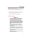
Test Leads – Markings
The 1744/1743 Logger includes built-in, labeled test leads for voltage
terminals L1 or A, L2 or B, L3 or C, and N, as well as two for the internal
power supply. The Flexi Set or current clamp sets are connected by a seven-pin
plug to the Logger. Color coding clips are provided for your convenience.
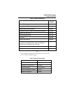
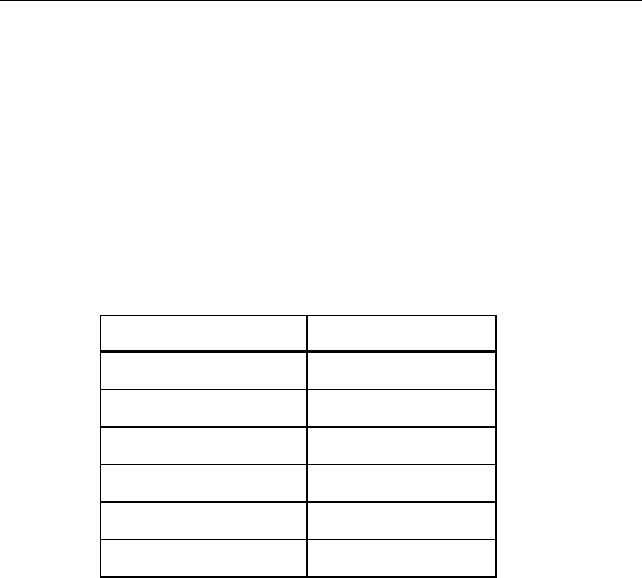
Table 5. Test Lead Markings
Test Leads Markings
Phase L1 or A L1 / A
Phase L2 or B L2 / B
Phase L3 or C L3 / C
Neutral wire N N
Supply “Supply”
Supply “Supply”
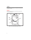
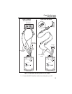
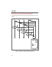
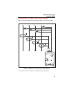
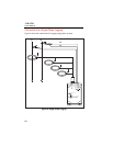
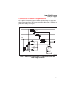
Connecting Current Probes
Connect current clamps and Flexi Set probes so that current will flow in the
direction marked by arrows on the probes. Current must flow from the energy
generator to the energy consumer (the load) in order to maintain a positive
active power. (The polarization of the test lead for neutral conductor current is
not significant, because the phase angle of the neutral conductor current is not
evaluated.)
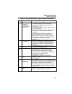
Note
Make sure the clip-on probes are connected to the appropriate phase:
V
L1
with I
L1
for a P-N measurement or V
L12
with I
L1
for a P-P
measurement.
Test Equipment Depot - 800.517.8431 - 99 Washington Street Melrose, MA 02176
FAX 781.665.0780 - TestEquipmentDepot.com