


Power Quality Logger
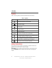
Safety Instructions
9
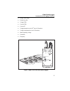
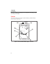
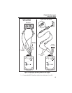
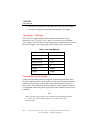
Table 4. 1744/1743 Power Quality Logger - Controls and Indicators
Item Name Description
A
Power supply
leads and
3-phase plus
neutral voltage
test leads
Power supply voltage range: 88-660 V ac or
100-350 VDC, 50 Hz / 60 Hz, 600 V CAT III.
Fixed installed voltage input cables for L1 or A,
L2 or B, L3 or C, N.
The highest permissible nominal voltage for power
supply input is 660 V.
The highest permissible nominal voltage for signal
input is 830 V in a 3-wire network with Delta
connection.
In a 4-wire network with Wye connection, the
highest permissible nominal voltage is 480 V.
When using PTs and CTs for measuring voltage
and current in a medium-voltage network, refer to
the IEC 60044 international standard for
guidelines.
B
RS232
interface port
The serial RS232 interface is used to communicate
with a PC. The Logger is connected to the PC’s
serial port (or a modem for remote communication)
using the interface cable. Use a USB adapter if
necessary.
C
START/STOP
The START/STOP button is used to start or end
switch-operated logging sessions.
D
Channel LEDs
The logging channel LEDs indicate whether the
applied voltages and currents are within the
nominal range set using the PQ Log software.
Continuously on = Logging signal in nominal range
Short blinks = No or low-level signal
Long blinks = Overload
E
Power status
LED
Continuously on = Power supply voltage in
permissible range
Off = No power
F
Connector for
Flexi Set or
current clamps
Flexi sets or current clamps are detected
automatically at power-up. If you change the current
probe type, be sure to remove and restore power so
the Logger will detect the new current probe.
Nominal ranges for the Flexi Set are 15 A, 150 A,
1500 A, and 3000 A ac. Nominal input for current
clamps is 0.5 V.
G
Logging status
LED
Continuously on = Logging in progress
Blinking = Logging stopped or not started