


LED DescriptionPackage Contents
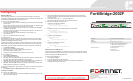
FortiBridge 2002F
USB2
CONSOLE2
MODEM2
MGMT2
INT3
INT4
INT3
INT4
EXT3
EXT4
EXT3
EXT4
HA2
PWR2
NORMAL2
BYPASS2
MODE2 RESET2
FortiGate
USB1
CONSOLE1
FortiGate
MODEM1
MGMT1
INT1
INT2
INT1
INT2
EXT1
EXT2
EXT1
EXT2
HA1
PWR1
NORMAL1
BYPASS1
MODE1 RESET1
DISCONNECT TWO POWER SUPPLY CORDS
BEFORE SERVICING
DISCONNECT TWO POWER SUPPLY CORDS
BEFORE SERVICING
Ground
AC power
connection
Power button Power button
AC power
connection
USB1
Console1
Modem1
Management1
LEDs
USB2
Console2
Modem2
Management2
LEDs
INT1 and
INT2
EXT1 and
EXT2
INT3 and
INT4
EXT3 and
EXT4
Mode1
Reset1
Mode2
Reset2
LEDs LEDs
Interface Description
Connecting
Administrator user name admin
Administrator password (none)
NAT/Route mode
Management1 192.168.1.99
Management2 0.0.0.0
To reset the unit to the factory defaults, in the CLI type the command:
execute factory reset
FortiG ate-30B
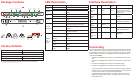
Tools and Documenation
Copyrig ht 2010 For tinet Incor porated. All rights reser ved.
Trademar ks
Product s mentioned in this do cument are trademarks.
QuickStart Guide
Straight-through
Ethernet cable
Power cable x2
DB9-RJ45 Serial
cable
REGISTER
FortiBridge 2002F
USB2
CONSOLE2
MODEM2
MGMT2
INT3
INT4
INT3
INT4
EXT3
EXT4
EXT3
EXT4
HA2
PWR2
NORMAL2
BYPASS2
MODE2RESET2
FortiGate
USB1
CONSOLE1
FortiGate
MODEM1
MGMT1
INT1
INT2
INT1
INT2
EXT1
EXT2
EXT1
EXT2
HA1
PWR1
NORMAL1
BYPASS1
MODE1RESET1
SFP SX x4
Factory Defaults
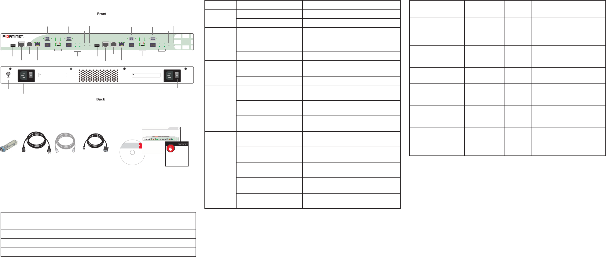
LED State Description
Power
Green The unit is powered on.
Off The unit is powered off.
Normal
Green The unit is being used in Normal
mode.
HA
Green The unit is being used in a HA cluster.
Off The unit is in stand-alone mode.
Bypass
Green Bypass network activity at this inter-
face.
Off Normal status.
INT and
EXT LEDs
Green The correct cable is in use and the
connected equipment has power.
Green ashing Network data is being sent or re-
ceived.
Off No link established or the interface
has been turned off.
MGMT1
and
MGMT2
Ports
Link/Activity (left) Green Port has power and network connec-
tion.
Link/Activity (left) Green
ashing
Network data is being sent or re-
ceived.
Speed (right) indicator is
Green
Connected at 1000 Mbps.
Speed (right) indicator is
Amber
The interface is connected at 100
Mbps.
Speed (right) indicator
is Off
The interface is connected at 10
Mbps.
Interface Type Speed Proto-
col
Description
Console1
and Con-
sole2
RJ-45 9600 bps
8/N/1
RS-232
serial
Connection to the manage-
ment computer. Provides
access to the command line
interface (CLI).
Modem1
and Mo-
dem2
RJ-11 Phone line for internal
modem.
USB1 and
USB2
USB USB Two optional connections to
a USB key for installation.
MGMT1
and
MGMT2
RJ-45 10/100/1000
Base-T
Ethernet Two management ports.
INT1, INT3,
EXT1, and
EXT3
LC
SFP
1000Base-SX Ethernet Fiber optic connections to
gigabit optical networks.
INT2,
INT4,
EXT2, and
EXT4
SFP 1GB-SX Ethernet Small form-factor pluggable
transceiver.
Connect the FortiBridge unit to the internal and external networks and the Forti-
Gate unit. Normally, you would use straight-through ethernet cables to connect
the FortiBridge unit. However, for some connections you may need a crossover
ethernet cable (for example, for compatibility with network devices that do not
support Auto MDI/MDIX).
• Connect the FortiBridge INT 2 interface to the FortiGate unit internal inter-
face.
• Connect the FortiBridge EXT 2 interface to the FortiGate unit external inter-
face.
• Connect the FortiBridge INT 1 interface to the internal network.
• Connect the FortiBridge EXT 1 interface to the external network.
• Turn on the FortiGate unit and any network equipment that was turned off.
• Connect the power cords at the back of the FortiBridge unit. Plug the other
end of the power cables into a grounded electrical outlet.
• The PWR and Bypass Mode LEDs turn on. After a short time, the Forti-
Bridge unit switches to Normal mode. The Bypass LED turns off and the
Normal LED turns on.