


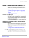

Power connection and configuration
FortiGate-5050-R Chassis Guide
01-30000-87717-20090108 23
http://docs.fortinet.com/ • Feedback
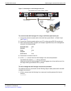
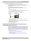
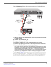
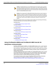
Figure 16: Connecting a FortiGate-5050 power input connector to a FortiGate-5053 power
converter tray
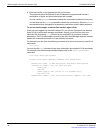
7 Make sure the power wires are secured to the chassis using the power wire fixture and
tie wraps if required.
8 If required, label the black wires -48V.
9 If required, label the red wires RTN.
10 Re-attach the protection plate to the FortiGate-5050 power input connector.
11 Attach the clear plastic cover to the back of the FortiGate-5053 power converter tray.
12 Connect the FortiGate-5053 power converter tray to AC power.
Only connect the power supplies that are installed in the FortiGate-5053 to AC power.
For example, if your FortiGate-5053 includes two FortiGate-5020/5050 power supplies,
the power supplies will be installed in slots 1 and 2. In this case you should only
connect AC in connectors 1 and 2 to AC power. If your FortiGate-5053 power converter
tray contains three power supples, connect all three AC in connectors to AC power.
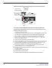
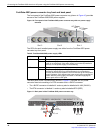
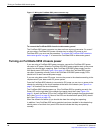
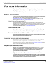
The photograph in Figure 17 shows the back panel of a FortiGate-5053 wired to provide
power to a FortiGate-5050 chassis. This photograph also shows the clear back cover of
the FortiGate-5053 installed. You should install this cover using the mounting hardware
provided. Install the cover after connecting the power but before turning the power on.
INPUT A
24
AMP
-48V
RTN (-DC IN)
Red RTN to
FortiGate-5053
RTN
Black -48V
VDC to
FortiGate-5053
-48 VDC
-48V
(-DC in)
(black)
Positive (RTN) (red)
Power wire
fixture
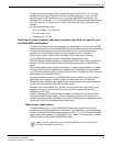
AC in
V+
(RTN)
(RED)
V-
-48V
(BLACK)