


21
661M03 Series User Manual
Chapter 2 Installation Instructions
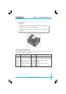
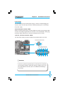
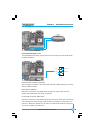
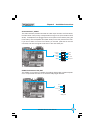
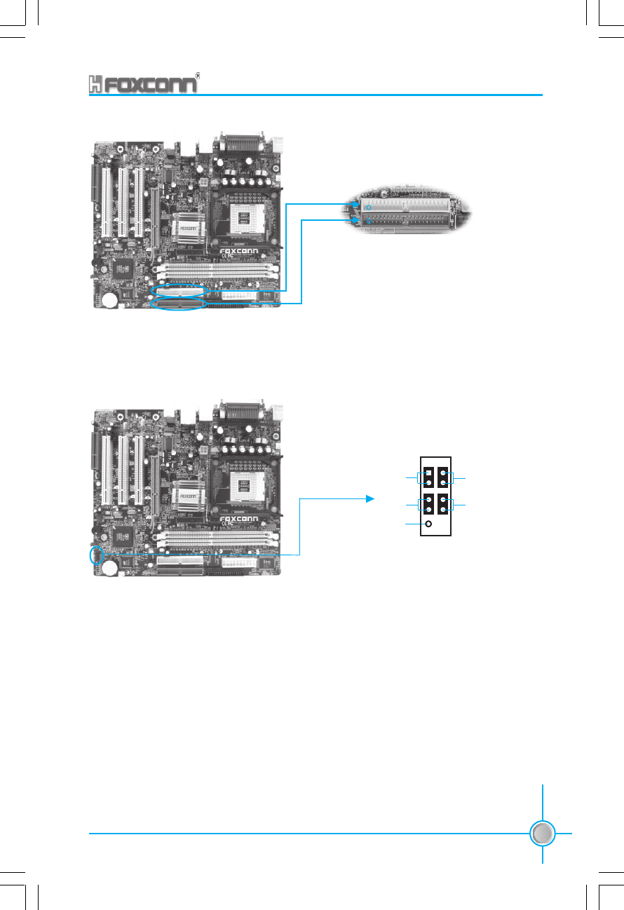
IDE 1
IDE 2
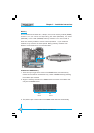
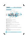
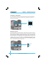
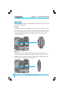
Front Panel Connector: F_P1
This motherboard includes one connector for connecting the front panel switch
and LED indicators.
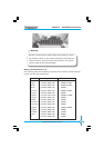
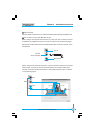
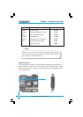
F_P1
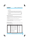
Hard Disk LED Connector (HD-LED)
The connector connects to the case’s IDE indicator LED indicating the activity
status of IDE hard disk.
Reset Switch (RESET)
Attach the connector to the Reset switch on the front panel of the case; the
system will restart when the switch is pressed.
Power LED Connector (PWR LED)
Attach the connector to the power LED on the front panel of the case. The Power
LED indicates the power supply’s status. When the system is in S0 status, the
LED is on. When the system is in S1 status, the LED is blink; When the system
is in S3 or S5 status, the LED is off.
1
NC
HD-LED
RESET
PWR-LED
PWR-SW
1
+
-
+
-