


System configurator and order-information guide
PRIMERGY Econel30 Status 2003-10-28
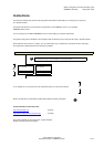
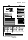
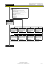
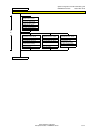
Configuration diagram for "PRIMERGY Econel30" system unit
SIDE VIEW
FRONT VIEW
System unit ( I )
Pentium 4 / Celeron
Standard
Power supply
Processor ( II ) Memory ( III ) 5.25"x1.6" DVD
Extension slots
5.25"x1.6"
Graphics ( IV )
SCSI Controller ( VII )
Disk array
Communication/Network ( IX )
5.25"x1.6"
Miscellaneous ( X )
3.5"x1" Floppy disk
AGP short
Accessible drives (V)
PCI 32-Bit / 33MHz, long Hard disks ( VI )
PCI 32-Bit / 33MHz, long IDE/SCSI - 3.5"x1"
PCI 32-Bit / 33MHz, long IDE/SCSI - 3.5"x1"
PCI 32-Bit / 33MHz, long
IDE/SCSI - 3.5"x1"
PCI 32-Bit / 33MHz, long IDE/SCSI - 3.5"x1"
PCI 32-Bit / 33MHz, long
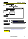
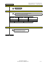
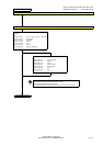
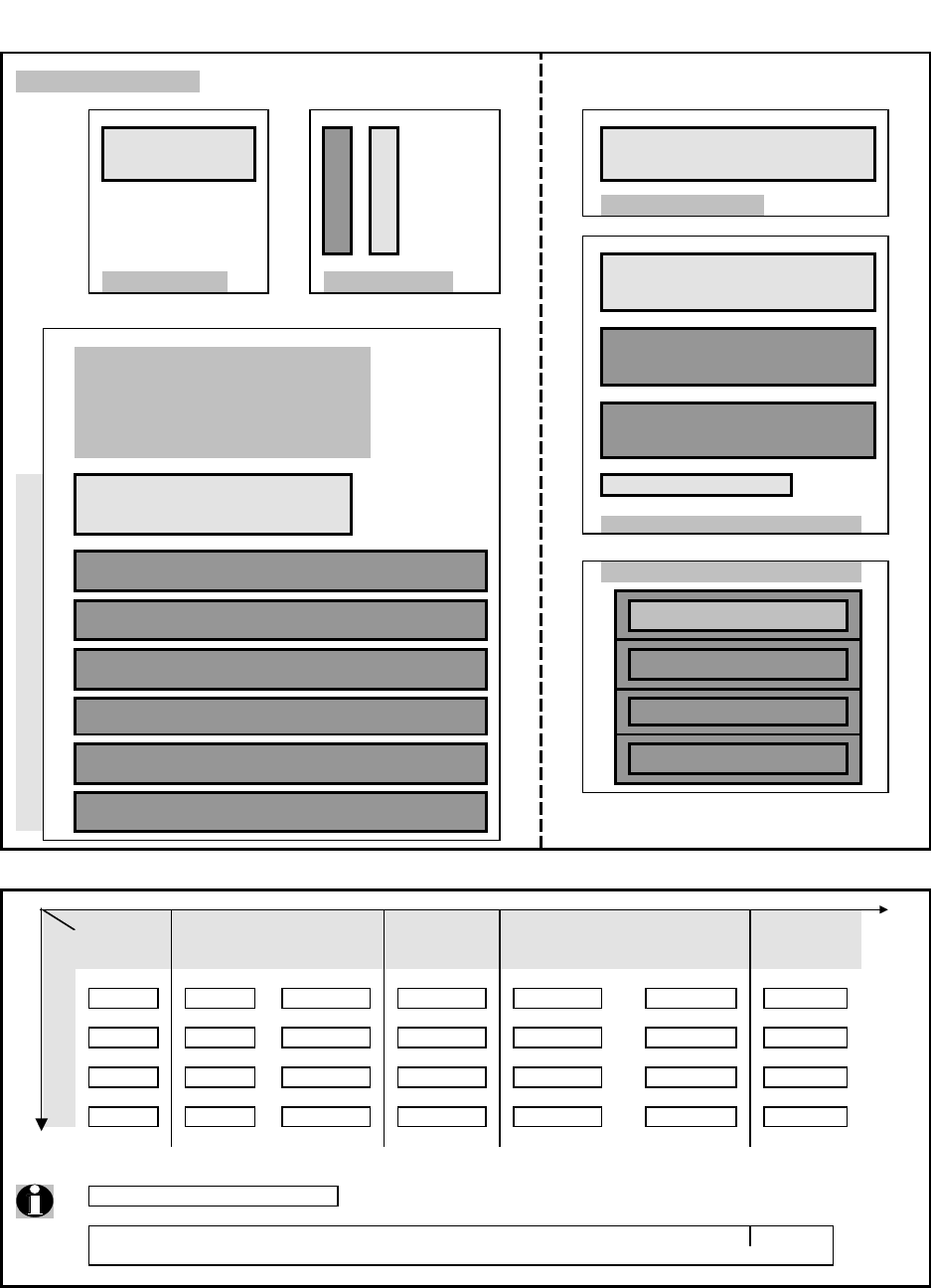
Recommendation of HD extension
Number of HDs
4
No 1
No 2
No 3 1)*
No 4 1)*
onb. = onboard MA = Master
Ch = Channel SL = Slave
All needed cables are enclosed.
Depending on the number and type of HDs, the chart above shows the connection of HDs
to the on-board IDE Controller, to the IDE RAID cards and to the SCSI controller card respectively.
1) * A second RAID Controller can only later be ordered as -L part number.
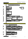
onb. MA
1.RAID MA Ch2 ID 1 (opt.)
2.RAID MA Ch1 ID 2 (opt.)
onb. MA onb. MA RAID MA Ch1
- -
- - -
MIXED
IDE
MIXED
IDE
Standard
IDE
onb. MA
Standard
IDE or
RAID
IDE
RAID MA Ch1 RAID MA Ch1
HD-Bays
-
- onb. SL RAID MA Ch2 - onb. SL
RAID MA Ch2 RAID MA Ch2 2.RAID MA Ch2 ID 3 (opt.)
1 2 1-43
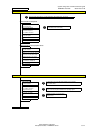
Bank 1
Bank 2
2
1
4
3
PCI-Bus
1
2
3
4
6
5
or
RAID
IDE SCSI
1.RAID MA Ch1 ID 0 (std.)
Fujitsu Siemens Computers
Enterprise Products - PRIMERGY Server
3 of 11