


9
FTP-628MCL Series
NOT FOR NEW
DESIGN
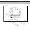
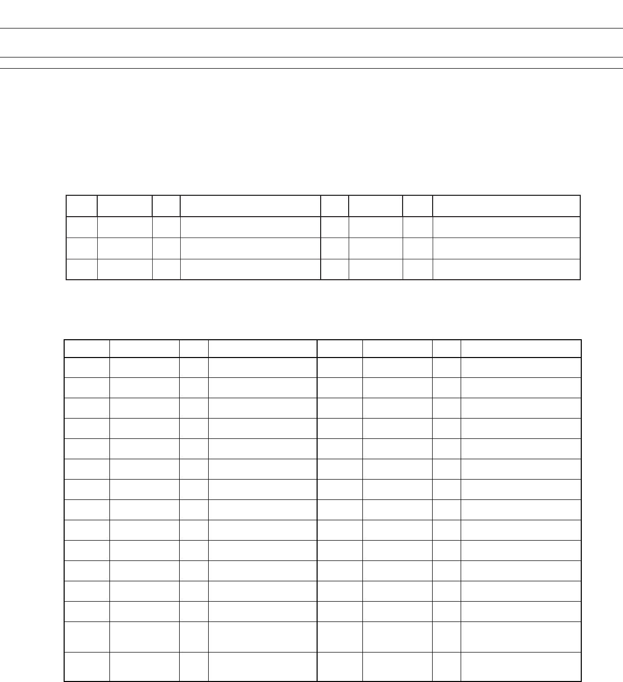
■ CONNECTOR PIN ASSIGNMENT
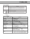
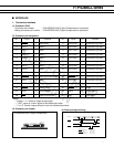
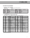
1. Connector for power supply (CN1)
Part number : B6P-VH (J.S.T) or equivalent (board side)
Mating Connector : VHR-6N
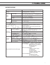
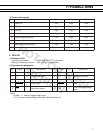
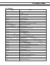
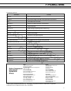
2. Connector for printer mechanism connection (CN3)
Part number : 52030-3010 (made by Molex) or equivalent (board side)
.oNlangiSO/I.oNstnetnoC.oNlangiSO/I.oNstnetnoC
15V+- cigolrofylppusrewoP2DNG-dnuorG
3DNG-dnuorG4DNG-dnuorG
5HV+- rotomdaehrofylppusrewoP6HV+- rotomdaehrofylppusrewoP
No. Signal I/O Contents No. Signal I/O Contents
1 PHK — Photo interrupter (cathode) 2 VSEN O
Power supply for paper senor
3 PHE I Photo interrupter (emitter) 4VH O
Head driving power supply
5VH O
Head driving power supply
6 GNC —
Ground for head
7 GND —
Ground for head
8 DIN O
Data input
9 LAT O Data latch 10 CLK O
Clock
11 STB6 O Enable 6 12 STB5 O
Enable 5
13 STB4 O Enable 4 14 VDD O
Logic Power supply
15 STB3 O Enable 3 16 STB 2 O
Enable 2
17 STB1 O Enable 1 18 TH I
Thermistor
19 TH I Thermistor 20 GND —
Ground for head
21 GND —
Ground for head
22 VH O
Head driving power supply
23 VH O
Head driving power supply
24 N.C. —
Open terminal
25 SW1 O Head open switch* 26 SW2 I Head open switch*
27 MT/B O Stepping motor coil 28 MT/B O Stepping motor coil
excitation signal B excitation signal B
29 MT/A O Stepping motor coil 30 MT/A O Stepping motor coil
excitation signal A excitation signal A
* on MCL003 and MCL004 models