8
FTP-639MCL054/353/354-R
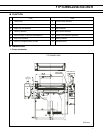
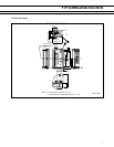
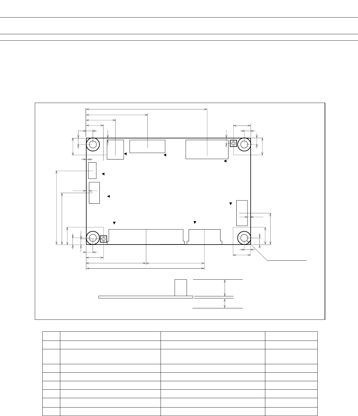
1. External Dimension Chart of the Control Board
EXTERNAL DIMENSION SPECIFICATIONS■
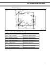
No. Name Function Remarks
CN1 Power connector To connect +24V and +5V power supply -
CN2 Connector for RS-232C interface control
signal connection
To connect RS-232C interface and control
signal
depends on models
CN3 Near end switch connector To connect Near End detection switch -
CN4 Reserved connector -
CN5 USB interface connector To connect USB interfaces depends on models
CN6 Head connector To connect the head
CN7 Transport motor connector To connect the transport
CN8 Cutter connector To connect the cutter depends on models
PRELIMINARY
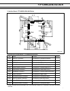
2. Connector Types on Control Board
8
3
1.448
3
8
10
1
CN7
CN8
30
CN6
27.5
55.45
27.95
8
3
1.285
3
8
13.653
28.702
56.705
CN5
9
1
CN2
CN1
2.5
8
3
8
14.605
3
8
2.5
24.13
34.607
8
3
1
3
1
3
CN4
CN3
1
1
1
3
4
1
Ø 3.3 NTH rand Ø 6.0
1
Part side H=15 mm (max.)
Solder side H=5 mm (max.)
Substrate t=1.2 mm
Unit: mm
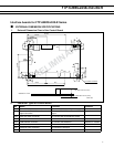
Interface boards for FTP-629DSL300-R Series


