


Diagram and user-selectable options (on NP models only)
Below is a diagram of the main board of SCSI disk drives and also a summary of the user-selectable options including guidelines for
installation of the drives.
This setting applies only for NP model drives.
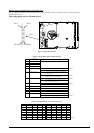
Figure 1. Option select terminal
Table 2. CN2 Terminal Setting (on NP models only)
Pin #
Setting Item
Function
1-2 SCSI ID 0 See Table 3.
3-4 SCSI ID 1
5-6 SCSI ID 2
7-8 SCSI ID 3
9-10 Write protect Open ……Write operation is enabled. (default)
Short
……Write operation is disabled.
11-12 Motor start mode Open ……Starting of motor is controlled with START/STOP
UNIT command.
Short
……Motor is started immediately after power supply is
turned on or microcode is downloaded.
(default)
13-14 Force Narrow Open ……16-bit bus mode (default)
Short
……Pull upper 8bits and parity internally when drive is
connected to Narrow SCSI bus.
15-16 Force Single Ended Open ……Follows DIFFSNS signal level on SCSI bus. (default)
Short
……Single-Ended mode
17 GND
18, 19 N.C
20 IDD Reset Input signal
21-22 Remote LED Output signal
23-24 Terminal power supply Open ……Drive does not supply terminator power to SCSI bus.
Short
……Drive supplies terminator power to SCSI bus. (default)
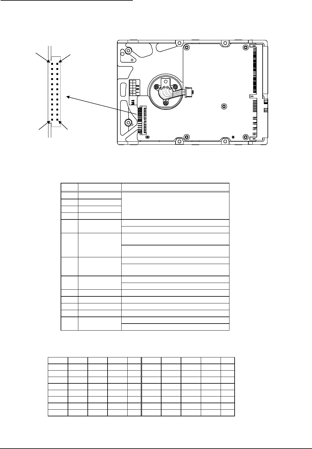
Table 3. SCSI ID Setting on CN2 (on NP models only)
Pin 1-2 Pin 3-4 Pin 5-6 Pin 7-8 ID Pin 1-2 Pin 3-4 Pin 5-6 Pin 7-8 ID
Open Open Open Open 0 Open Open Open Short 8
Short Open Open Open 1 Short Open Open Short 9
Open Short Open Open 2 Open Short Open Short 10
Short Short Open Open 3 Short Short Open Short 11
Open Open Short Open 4 Open Open Short Short 12
Short Open Short Open 5 Short Open Short Short 13
Open Short Short Open 6 Open Short Short Short 14
Short Short Short Open 7 Short Short Short Short 15 (default)
Pin 1
CN2
Pin 2
Pin 23
Pin 24