


Diagnostics and Maintenance
6-12 C141-E219
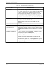
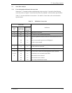
Table 6.2 System-level field troubleshooting
Item Recommended work
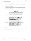
DC power level Check that the DC voltage is within the specified range (±5%).
For +5V DC, measure the voltage between pin 20 (+5V) of the interface
connector and the nearest PCA mounting screw (GND) from the
interface connector, and confirm the value is from 4.75 to 5.25 VDC.
For +12V DC, measure the voltage between pin 2 (+12V) of the
interface connector and the nearest PCA mounting screw (GND) from
the interface connector, and confirm the value is from 11.4 to 12.6 VDC.
Electrical noise Make sure the maximum ripple peak-to-peak value of +5V DC is within
250 mV and +12V DC is within 250 mV.
Make sure the high frequency noise (over 20 MHz) is less than
100 mVp-p.
Drive selection address Check that the disk drive selection address is set correctly.
System cables Check that all system cables are connected correctly.
System diagnostic test When possible, execute the system level diagnostic routine as explained
in the host computer manual. This gives a detailed report of a possible
fault.
Intermittent or nonfatal errors Check the AC voltage from the power supply. Check the DC voltage
level at the power connector for the disk drive.
If the AC voltage level is abnormal or there is a lot of electrical noise,
notify the user of the error.
If the DC voltage level is unstable, replace the power supply unit.
If possible, replace the disk drive. If replacing the disk drive does not
eliminate the error, the removed disk drive is probably not faulty. To
continue error analysis, refer to the hardware and software manuals
supplied with the system.