


Contents
xiv C141-E235
Illustrations
Figures
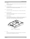
Figure 1.1 FC model drives outer view......................................................... 1-5
Figure 1.2 Example of FC-AL system configuration.................................... 1-7
Figure 3.1
Cylinder configuration ................................................................. 3-2
Figure 3.2 Spare area in cell.......................................................................... 3-4
Figure 3.3 Alternate cylinder......................................................................... 3-4
Figure 3.4 Track format................................................................................. 3-5
Figure 3.5 Track skew/head skew ................................................................. 3-6
Figure 3.6 Sector format................................................................................ 3-6
Figure 3.7 Alternate block allocation by FORMAT UNIT command ........ 3-11
Figure 3.8 Alternate block allocation by REASSIGN BLOCKS
command.................................................................................... 3-12
Figure 4.1
Dimensions................................................................................... 4-2
Figure 4.2 HDD orientations ......................................................................... 4-3
Figure 4.3 Mounting frame structure............................................................. 4-4
Figure 4.4 Limitation of side-mounting ........................................................ 4-5
Figure 4.5 Surface temperature measurement points.................................... 4-6
Figure 4.6 Service clearance area.................................................................. 4-7
Figure 4.7 Current waveform (+12 VDC)..................................................... 4-8
Figure 4.8 AC noise filter (recommended).................................................... 4-9
Figure 4.9 Connector location ....................................................................... 4-9
Figure 4.10 SCA2 type connector ................................................................. 4-10
Figure 5.1
Checking the HDD connection (A).............................................. 5-7
Figure 5.2 Checking the HDD connection (B).............................................. 5-8
Figure 6.1
Revision label (example) ............................................................. 6-8
Figure 6.2 Indicating revision numbers......................................................... 6-9
Figure 6.3 Test flowchart............................................................................. 6-10
Figure 7.1
Format of extended sense data..................................................... 7-2