MB3773
6
■
■■
■
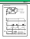
OPERATION SEQUENCE
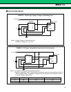
(1) When Vcc rises to about 0.8 V, RESET goes “Low” and RESET goes “High”.
The pull-up current of approximately 1 µA (Vcc = 0.8 V) is output from RESET.
(2) When Vcc rises to VSH ( := 4.3V) , the charge with CT starts.
At this time, the output is being reset.
(3) When C
T begins charging, RESET goes “High” and RESET goes “Low”.
After T
PR reset of the output is released.
Reset hold time: T
PR (ms) := 1000 × CT (µF)
After releasing reset, the discharge of C
T starts, and watch-dog timer operation starts.
T
PR is not influenced by the CK input.
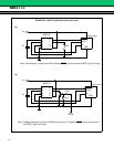
(4) C changes from the discharge into the charge if the clock (Negative edge) is input to the CK terminal
while discharging C
T.
(5) C changes from the charge into the discharge when the voltage of C
T reaches a constant
threshold ( := 1.4 V) .
(4) and (5) are repeated while a normal clock is input by the logic system.
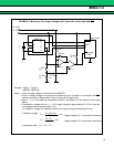
(6) When the clock is cut off, gets, and the voltage of C
T falls on threshold ( := 0.4 V) of reset on, RESET goes
“Low” and RESET goes “High”.
Discharge time of C
T until reset is output: TWD is watch-dog timer monitoring time.
T
WD (ms) := 100 × CT (µF)
Because the charging time of C
T is added at accurate time from stop of the clock and getting to the output
of reset of the clock, T
WD becomes maximum TWD + TWR by minimum TWD.
(7) Reset time in operating watch-dog timer:T
WR is charging time where the voltage of CT goes up to off
threshold ( := 1.4 V) for reset.
T
WR (ms) := 20 × CT (µF)
Reset of the output is released after C
T reaches an off threshold for reset, and CT starts the discharge,
after that if the clock is normally input, operation repeats (4) and (5) , when the clock is cut off, operation
repeats (6) and (7) .
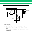
(8) When Vcc falls on V
SL ( := 4.2 V) , reset is output. CT is rapidly discharged of at the same time.
(9) When Vcc goes up to V
SH, the charge with CT is started.
When Vcc is momentarily low,
After falling V
SL or less Vcc, the time to going up is the standard value of the Vcc input pulse width in VSH or
more.
After the charge of C
T is discharged, the charge is started if it is TPI or more.
(10) Reset of the output is released after TPR, after Vcc becomes VSH or more, and the watch-dog timer starts.
After that, when Vcc becomes V
SL or less, (8) to (10) is repeated.
(11) While power supply is off, when Vcc becomes V
SL or less, reset is output.
(12) The reset output is maintained until Vcc becomes 0.8 V when Vcc falls on 0 V.


