Contents
C141-E245 xi
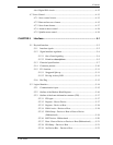
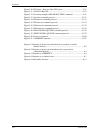
4.6.4 Digital PLL circuit ................................................................................4-12
4.7 Servo Control ...................................................................................................4-13
4.7.1 Servo control circuit..............................................................................4-13
4.7.2 Data-surface servo format .....................................................................4-15
4.7.3 Servo frame format................................................................................4-17
4.7.4 Actuator motor control..........................................................................4-18
4.7.5 Spindle motor control............................................................................4-19
CHAPTER 5 Interface..................................................................................... 5-1
5.1 Physical Interface..............................................................................................5-2
5.1.1 Interface signals ....................................................................................5-2
5.1.2 Signal interface regulation ....................................................................5-4
5.1.2.1 Out of band signaling.................................................................5-4
5.1.2.2 Primitives descriptions.............................................................5-5
5.1.3 Electrical specifications ........................................................................ 5-7
5.1.4 Connector pinouts...............................................................................5-10
5.1.5 P11 function........................................................................................5-11
5.1.5.1 Staggered Spin-up....................................................................5-11
5.1.5.2 Driving Activity LED ..............................................................5-11
5.1.6 Hot Plug .............................................................................................. 5-13
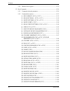
5.2 Logical Interface .............................................................................................5-14
5.2.1 Communication layers ........................................................................5-15
5.2.2 Outline of the Shadow Block Register................................................ 5-16
5.2.3 Outline of the frame information structure (FIS)................................5-17
5.2.3.1 FIS types ..................................................................................5-17
5.2.3.2 Register - Host to Device ......................................................... 5-17
5.2.3.3 Register - Device to Host ......................................................... 5-18
5.2.3.4 DMA Active - Device to Host..................................................5-18
5.2.3.5 DMA Setup - Device to Host or Host to Device
(Bidirectional) ..........................................................................5-19
5.2.3.6 BIST Active - Bidirectional .....................................................5-20
5.2.3.7 Data - Host to Device or Device to Host (Bidirectional) .........5-21
5.2.3.8 PIO Setup – Device to Host .....................................................5-21
5.2.3.9 Set Device Bits – Device to Host.............................................5-23


