


Interface
5-30 C141-E262
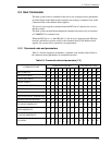
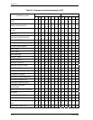
5.3.2 Command descriptions
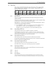
The contents of the shadow block registers to be necessary for issuing a command
and the example indication of the shadow block registers at command completion
are shown as following in this subsection.
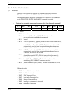
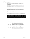
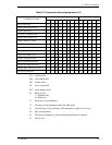
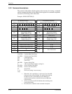
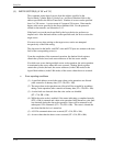
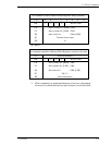
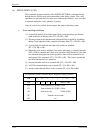
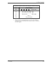
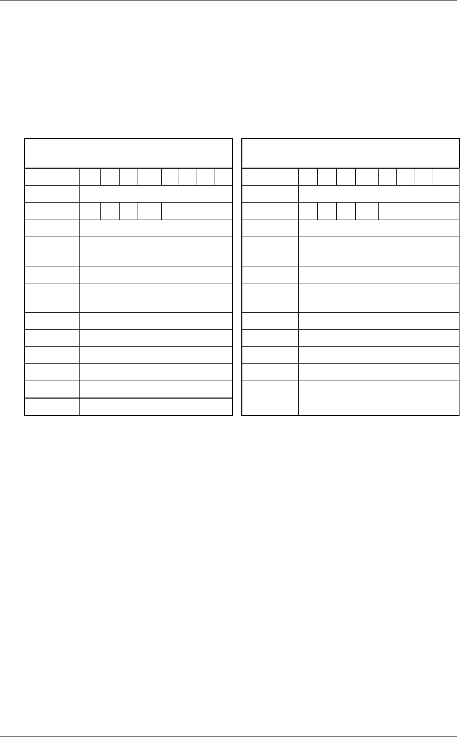
Example: READ SECTOR (S)
At command issuance
(Shadow Block Registers setting contents)
At command completion
(Shadow Block Registers to be read)
Bit 7 6 5 4 3 2 1 0 Bit 7 6 5 4 3 2 1 0
CM 0 0 1 0 0 0 0 0 ST Status information
DH x L x x HD No./LBA DH x L x x HD No./LBA
CH EXP LBA (47-40) CH EXP LBA (47-40)
CH
Start cylinder address
[MSB] / LBA (23-16)
CH
End cylinder address
[MSB] / LBA (23-16)
CL EXP LBA (39-32) CL EXP LBA (39-32)
CL
Start cylinder address
[LSB] / LBA (15-8)
CL
End cylinder address
[LSB] / LBA (15-8)
SN EXP LBA (31-24) SN EXP LBA (31-24)
SN Start sector No. / LBA (7-0) SN End sector No. / LBA (7-0)
SC EXP Transfer sector count (15-8) SC EXP X '00'
SC Transfer sector count (7-0) SC X '00'
FR EXP xx
FR xx
ER Error information
CH (EXP): Cylinder High Field (EXP)
CL (EXP): Cylinder Low Field (EXP)
CM: Command Field
DH: Device/Head Field
ER: Error Field
FR (EXP): Features Field (EXP)
L: LBA (Logical Block Address) setting bit
SN (EXP): Sector Number Field (EXP)
SC (EXP): Sector Count Field (EXP)
ST: Status Field
x, xx: Don't care (setting is not necessary).
Note:
1. When the L bit is specified to 1, the lower 4 bits of the DH
field and all bits of the CH field, CL and SN fields indicate
the LBA bits (bits of the DH filed are the MSB (most
significant bit) and bits of the SN field are the LSB (least
significant bit).
2. At error occurrence, the SC field indicates the remaining sector
count of data transfer.
3. Bit indication is omitted in each command description.