


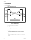
5.1 Physical Interface
C141-E262 5-7
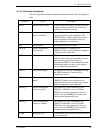
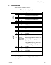
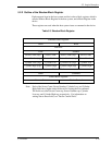
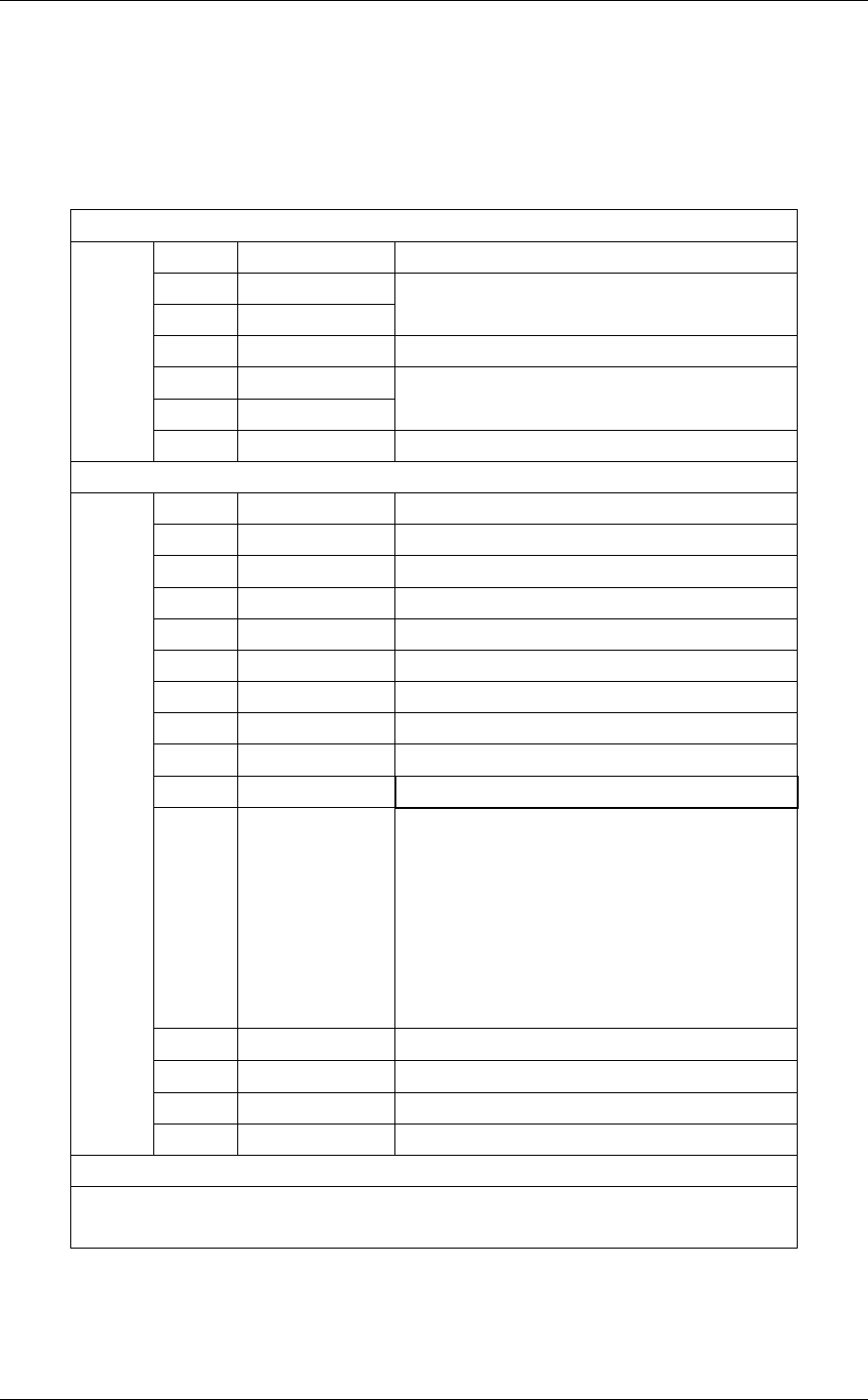
5.1.4 Connector pinouts
The pin definitions are shown in Table 5.1.
Table 5.1 Connector pinouts
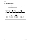
Signal segment key
S1 Gnd 2nd mate
S2 A+
S3 A-
Differential signal pair A from Phy
S4 Gnd 2nd mate
S5 B-
S6 B+
Differential signal pair B from Phy
Signal
segment
S7 Gnd 2nd mate
"Key and spacing separate signal and power segments"
P1 V33
N.C.(Open)
P2 V33
N.C.(Open)
P3 V33
N.C.(Open)
P4 Gnd 1st mate
P5 Gnd 2nd mate
P6 Gnd 2nd mate
P7 V5 5 V power, pre-charge, 2nd mate
P8 V5 5 V power
P9 V5 5 V power
P10 Gnd 2nd mate
P11 Staggered
Spin-up Mode/
Activity LED
• Staggered Spin-up mode detect for input
• Activity LED drive for output
For the specification of P11, see Section
5.1.5. (in next page)
When the host system does not use these
function, the corresponding pin to be mated
with P11 in the power cable receptacle
connector shall be grounded.
P12 Gnd
1st mate
P13 V12
N.C.(Open)
P14 V12
N.C.(Open)
Power
segment
P15 V12
N.C.(Open)
Power segment key
Notes:
Note) Since applying a single external supply voltage of 5 V enables this
drive to operate it is unnecessary to supply +3.3 V and +12 V
power supplies.