


C141-E045-02EN 4 - 19
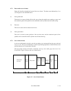
4.7.2 Data-surface servo format
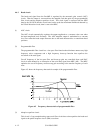
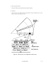
Figure 4.8 describes the physical layout of the servo frame. The three areas indicated by (1) to
(3) in Figure 4.8 are described below.
(1) Inner guard band
The head is in contact with the disk in this space when the spindle starts turning or stops, and
the rotational speed of the spindle can be controlled on this cylinder area for head moving.
(2) Data area
This area is used as the user data area SA area.
(3) Outer guard band
This area is located at outer position of the user data area, and the rotational speed of the
spindle can be controlled on this cylinder area for head moving.
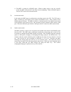
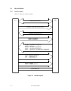
4.7.3 Servo frame format
As the servo information, the drive uses the two-phase servo generated from the gray code and
servo A to D. This servo information is used for positioning operation of radius direction and
position detection of circumstance direction.
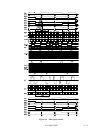
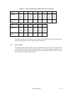
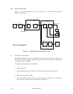
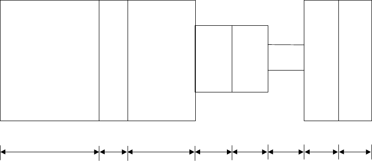
The servo frame consists of 5 blocks; write/read recovery, servo mark, gray code, servo A to
D and PAD. Figure 4.9 shows the servo frame format.
PAD
Servo
D
Servo
C
Servo
B
Servo
A
0.54 µs1.32 µs1.32 µs1.32 µs1.26 µs3.06 µs0.54 µs2.34 µs
Gray code
Servo
mark
Write/read
recovery
Figure 4.9 Servo frame format